Skip to the content
PCBKitNew board
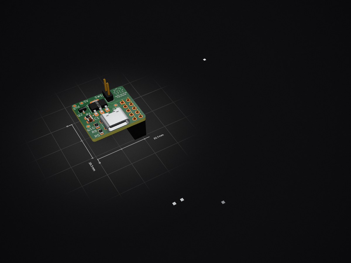
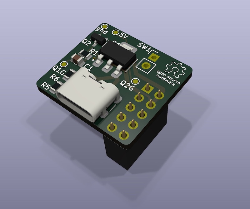
2 layers22.1 × 20.3 mmLatch Rasp, the printed circuit board in 3D

Mini HAT with a Push Button to Power the Raspberry Pi On and Off Safely, After the Shutdown Sequence Completes

Size
22.1 × 20.3 mm
Copper layers
2
Thickness
1.6 mm
Parts
20
Nets
15
Pads
53
Tracks, vias
90, 3
Pours
1
Routed
Yes
KiCad
KiCad 9.0 (file 20241229)
Created
18 Jan 2026
Updated
19 Jan 2026

Overview

Latch Rasp is an open-source printed circuit board by aresta, from the aresta/Rasp_latch_button repository on GitHub. It is a 2-layer board of 22.1 × 20.3 mm with 20 parts on 15 nets, routed with 90 tracks and 3 vias.

It is built around the AO3414 and NDT456P. Its parts include 6 resistors, 2 capacitors, 2 diodes, 2 transistors and 2 connectors.

Main components

2

README

README.md

Raspberry Pi Power Button HAT - Power On, Shutdown and Power off

Mini HAT with a Push Button to Power the Raspberry Pi On and Off Safely, After the Shutdown Completes.

  • When the Raspberry Pi is off, a button press powers it on.
  • When the Raspberry Pi is on, a button press initiates the shutdown sequence, and when it completes, cuts the power automatically.
  • An additional switch in the USB cable is not necessary; after the shutdown, the power is completely off.

Only shutdown sometimes is not enough. After the shutdown the Raspberry Pi enters a halted state, the operating system has ceased all activity, but the hardware remains powered. Most models continue to draw power (up to 1.5W for a Pi 4). The red Power LED often remains lit, and some peripherals, like a DSI display, can remain powered with the backlight active. In those cases is better to cut the power completely.

This little board is useful for home devices, like audio players or home theater systems, to avoid having to initiate the shutdown in the user interface, wait some time, and then cut off the power manually.

If you initiate the shutdown from the device user interface it works the same, after the shutdown sequence, it will cut the power.

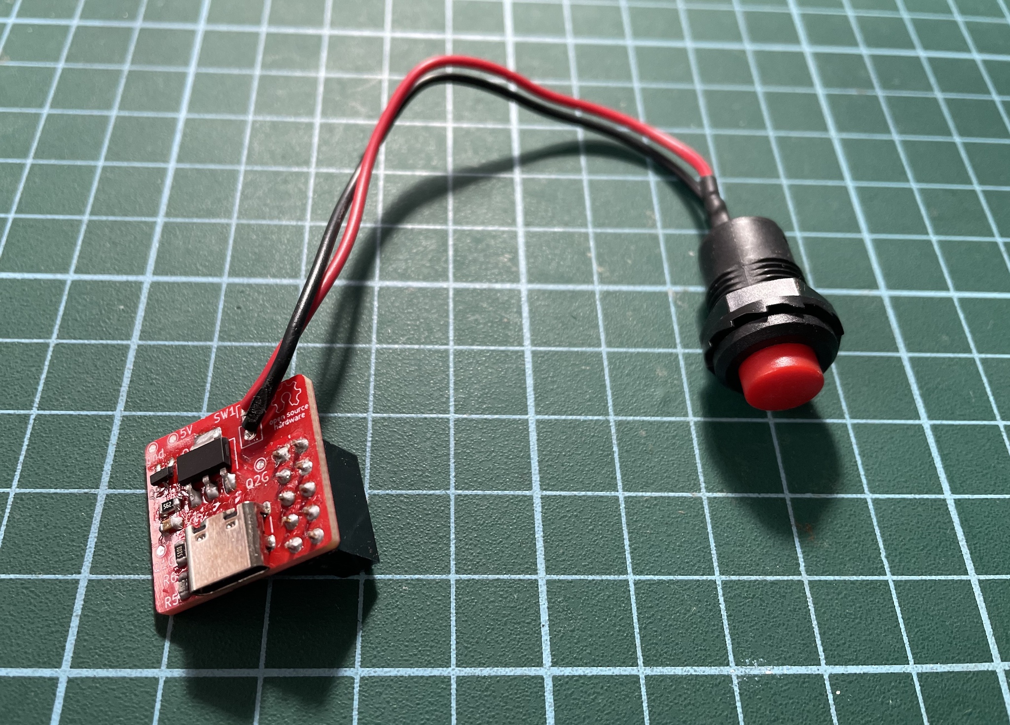
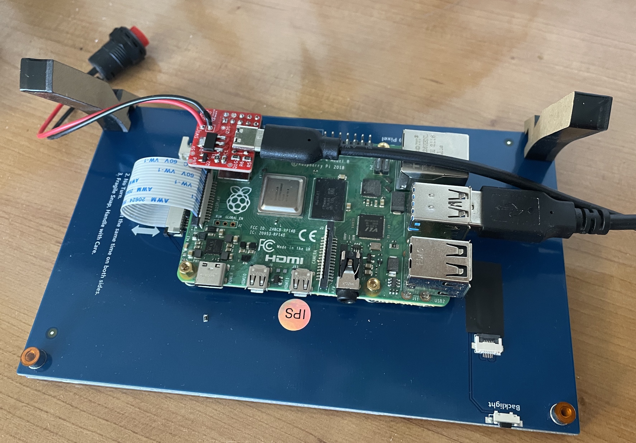
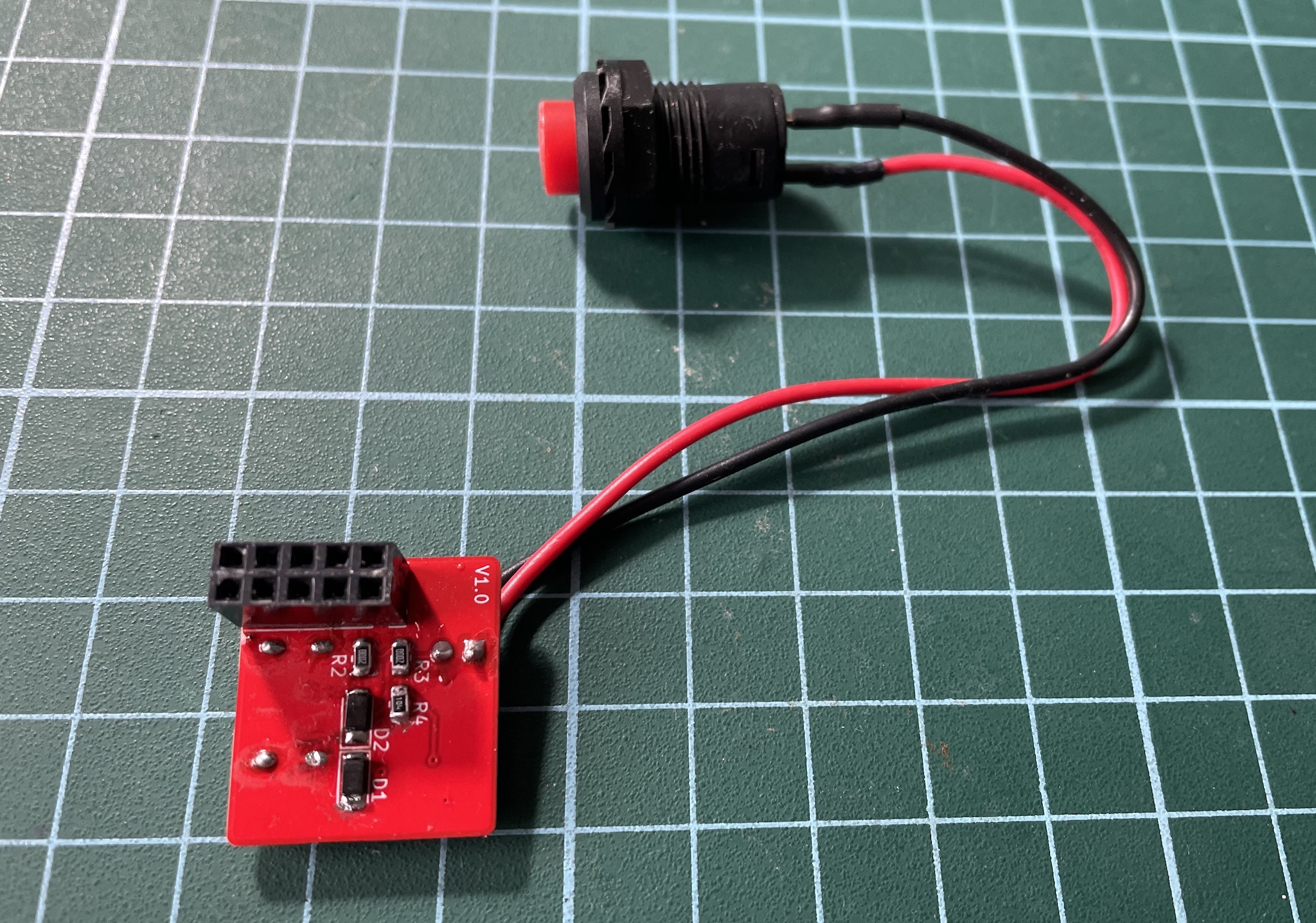
The Mini HAT:

  • USB-C power connector. Use only this connector to power the Raspberry Pi.
  • Push button. A push button of any size or type.
  • 5x2 socket to plug into the Raspberry Pi header. It provides access to GPIO2, GPIO3, and power pins.

GPIO pins and Overlays:

You have to configure GPIO 2 and 3 in the config.txt file. For power management, we specifically use these two specialized overlays:

  • gpio-shutdown:

    • What it does: Configures a GPIO pin to act like a keyboard's power button.
    • The Result: When the pin is triggered, it sends a KEY_POWER event to the system, which tells systemd to perform a clean, safe shutdown. It is much safer than simply pulling the power plug.
  • gpio-poweroff:

    • What it does: Reaches out to the "outside world" after the Pi has finished its shutdown process.
    • The Result: Once the Pi's software is completely halted, it flips the state of a GPIO pin. This is intended to signal an external circuit (like our HAT) that it is now safe to physically cut the electricity to the Pi.

GPIO 2: Shutdown (gpio-shutdown)

  • Add dtoverlay=gpio-shutdown to your config file to enable GPIO 2 as the shutdown trigger.
  • Configuration: Add this line to your config file:
    dtoverlay=gpio-shutdown,gpio_pin=2,active_low=1,gpio_pull=up

GPIO 3: Power-Off Signaling (gpio-poweroff)

  • Add dtoverlay=gpio-poweroff to your config file to enable GPIO 3 as the poweroff trigger.
  • The pin will transition to its active state (LOW) only after the kernel has finished shutting down, ensuring no SD card corruption occurs
  • active_low=1: The pin is HIGH (3.3V) while the Pi is running and transitions to LOW (0V) once it is safe to cut power
  • Configuration: Add this line to your config file:
    dtoverlay=gpio-poweroff,gpiopin=3,active_low=1

For example:

bash
[all]
# Add your shutdown/poweroff overlays here
dtoverlay=gpio-shutdown,gpio_pin=2,active_low=1,gpio_pull=up
dtoverlay=gpio-poweroff,gpiopin=3,active_low=1

Config file Location

Configure the behaviour of the GPIO pins in the Raspberry Pi config file:

  • Raspberry Pi OS Bookworm (and newer): The file is located at /boot/firmware/config.txt.
  • Older OS Versions (Bullseye and earlier): The file is located at /boot/config.txt.
  • On another computer: If you insert the SD card into a PC or Mac, the file is located in the root directory of the small partition named boot or bootfs.

The circuit

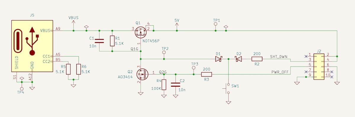
Basic power latch circuit combined with the shutdown and poweroff GPIO's to manage the power off sequence.

  • Before the button is pressed Q1 is off because R1 keeps the gate at the same voltage than the source. There is no power at the 5V pin.
  • When the button is pressed, it brings the gate of Q1 to GND, activating the power. C1 prevents button bouncing.
  • When the Rasperry Pi boots it keeps the GPIO 3 (power_off pin) up, keeping Q2 on, what keeps Q1 also on.
  • When the Rasperry Pi is on and the button is pressed again, it sends a LOW signal to the GPIO 2 (sht_dwn pin), what initiates the shut down sequence.
  • When shut down sequence completes, the GPIO 3 (power_off pin) goes LOW, what switchs Q2 off, and therefor Q1 switchs off also, and the power gets cut off.

Restrictions

  • The maximum current that the board can handle is about 7A, but the maximum that you can get from this USB-C connector is 3A (15W). It should be enough for most applications with few basic peripherals.
  • The HAT takes the first 10 pins of the header, to use two 5V and two GND pins, and also for stability. It means that the pins of GPIO's 2,3,4,14,15 are not available in the header for other uses.
  • Conflict with I2C: Because Pin 5 (GPIO 3) is the only pin that can wake the Pi from a deep sleep, using it for a shutdown button will conflict with I2C devices.
  • There are no power or USB protections in the PCB. Use at your own risk!

Compatibility with Raspberry Pi Versions

The overlays used for shutdown and power-off are supported on almost all models, provided you are using a modern operating system (Raspbian Stretch 2017 or newer).

  • Raspberry Pi 4 & 5: Fully compatible. Note that while the physical pinout is identical, the Raspberry Pi 5 uses a new RP1 chip for I/O; however, the kernel handles these device tree overlays so they function the same way as on older boards.
  • Raspberry Pi 2, 3, Zero, and B+: Fully compatible with the standard 40-pin header.
  • Original Raspberry Pi 1: Probably not compatible without modifications. On these specific early models, GPIO 1 is used for shutdown instead of the modern standard GPIO 3

Anyway, I have only tested it with a Raspberry Pi 4b.

There are no power or USB protections in the PCB. Use at your own risk!

Parts

20
QtyValueFootprintReferences
35.1KResistor_SMD:R_0805_2012MetricR1, R5, R6
210nCapacitor_SMD:C_0805_2012MetricC1, C2
2200Resistor_SMD:R_0805_2012MetricR2, R3
2D_SchottkyDiode_SMD:D_1206_3216MetricD1, D2
1100KResistor_SMD:R_0805_2012MetricR4
15VTestPoint:TestPoint_Pad_D1.0mmTP1
1AO3414Package_TO_SOT_SMD:SOT-23Q2
1Conn_02x03_Counter_ClockwiseConnector_PinSocket_2.54mm:PinSocket_2x05_P2.54mm_VerticalJ2
1LOGO000_victor:Open_HardwareG***
1NDT456PPackage_TO_SOT_SMD:SOT-223Q1
1Q1GTestPoint:TestPoint_Pad_D1.0mmTP2
1Q2GTestPoint:TestPoint_Pad_D1.0mmTP3
1SW_PushConnector_PinHeader_2.54mm:PinHeader_1x02_P2.54mm_VerticalSW1
1USB_C_Receptacle_PowerOnly_6PConnector_USB:USB_C_Receptacle_GCT_USB4125-xx-x-0190_6P_TopMnt_HorizontalJ5
1gndTestPoint:TestPoint_Pad_D1.0mmTP4

Questions

How big is the Latch Rasp PCB?

It measures 22.1 × 20.3 mm and has 2 copper layers, 1.6 mm thick.

What parts does the Latch Rasp use?

20 parts, built around the AO3414 and NDT456P. The full list of its parts is on this page, with links to each part's symbol and footprint where PCBKit's library has them.

Where can I download the Latch Rasp KiCad files?

From the aresta/Rasp_latch_button repository on GitHub, at the commit this page was made from: the board is Latch_Rasp.kicad_pcb and its schematic Latch_Rasp.kicad_sch. PCBKit opens the board in the browser, with nothing to install.

Can I use the Latch Rasp design in my own project?

Its repository states no licence, so its author keeps all rights: ask aresta before reusing the design.

Similar boards

  • 6 layers102.6 × 62.6 mmSPANNUNG BLE 1, the printed circuit board in 3D

    SPANNUNG BLE 1

    joeheinz/Tensosense-Schem

    This is my personal design project...

    139 parts
  • 2 layers87.9 × 78.1 mmSneak100 main board v2, the printed circuit board in 3D

    Sneak100 main board v2

    Eryk-Mozdzen/minisumo-sneak100

    Autonomous minisumo robot

    144 parts4
  • 4 layers86 × 145 mmCopper layers, the printed circuit board in 3D

    Copper layers

    JCastel358/Eltec406mca

    code for industrial automation process

    206 parts1
  • 2 layers100 × 100 mmRobot-5A, the printed circuit board in 3D

    Robot-5A

    jgraulle/robot-pcb

    193 parts
  • 2 layers66.9 × 74.5 mmDeskHop Rev1, the printed circuit board in 3D

    DeskHop Rev1

    hrvach/deskhop

    Fast Desktop Switching Device

    20 parts7.9kGPL-3.0
  • 2 layers86.4 × 64.8 mmSlot machine, the printed circuit board in 3D

    Slot machine

    google/google-ctf

    Google CTF

    20 parts5.1kApache-2.0
  • 2 layers36.2 × 26.8 mmEsp32 minimal, the printed circuit board in 3D

    Esp32 minimal

    atopile/atopile

    Design circuit boards with code! ✨ Get software-like design reuse 🚀, validation, version control and collaboration in hardware; starting with electronics ⚡️

    20 parts4kMIT
  • 2 layers108.1 × 393.8 mmSweep compact ble, the printed circuit board in 3D

    Sweep compact ble

    davidphilipbarr/Sweep

    Sweep - a small promicro based keyboard inspired by the Ferris.

    20 parts2.1k