2 layers
Encoder
byrantech/laptop
anyon_e, a highly integrated, high end, open source laptop. Attempt the impossible.
7 parts4.3kMIT

 Ardakilic/dummifier32
Dummifier: A USB-3 to USB-2 with USB Type-C Port adapter where the devices fail to follow standards
Dummifier is an open-source printed circuit board by Ardakilic, from the Ardakilic/dummifier repository on GitHub, published under the GPL-3.0 licence. It is a 2-layer board of 25.1 × 11.1 mm with 7 parts on 22 nets, routed with 130 tracks and 6 vias.
Its parts include 4 resistors, 2 connectors and 1 capacitor.
Dummifier: A USB-3 to USB-2 with USB Type-C Port adapter where the the engineers fail to follow basic standards while designing the boards.
You just plug this dongle thingy between your device and your usb-c cable, and it'll start working as you expected.
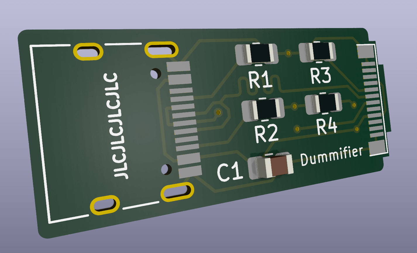
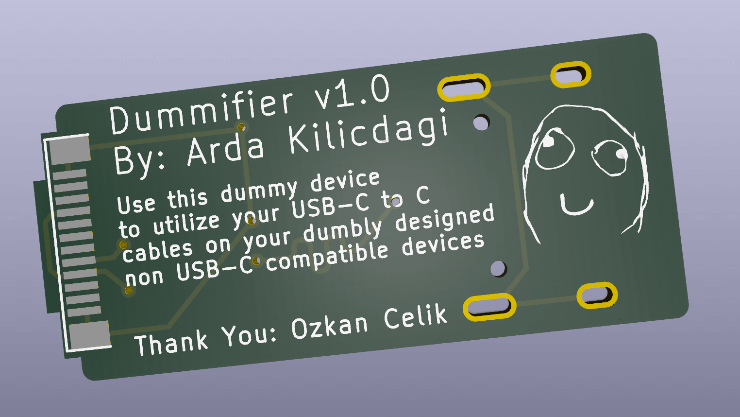
First of all, I needed this. Some devices that I own, such as Planck keyboard, Anbernic RG351P utilized USB-C port, but they only worked when a cheap USB-C to USB-A cable was utilized, or through a USB Hub. They were not working at all with the USB-C cable I carry around, or getting wrong voltage and being burned. I burned my GP micro USB (I was using a USB-C to micro USB converter) battery charger because of this.
Additionally, I made some mods for Nintendo new 2DS XL for USB-C mod, and some cables were not working correctly.
Even newer Raspberry Pi Pico clones were having this issue.
The common workaround for this issue is using a USB Hub, or Cheap, non-standard, USB 2.0 Type A to USB-C 4 pin cables.
These cables are getting harder to find day by day.
I used to make some dummy cables for this purpose. Like this, this and this. Functionality wise, they were all working, but damn they were ugly! Also, they had one thing in common. These populated 5.1K ohm resistors in CC1 and CC2 pins.
When I checked the USB standards (page 38 and 76) , I realized these were necessary on female end so that the devices could talk to each other with USB 2.0 standards and get 5V instead of PD voltages.
After I burned my GP battery charger, I decided to tinker with Kicad and make my own adapter.
Some people even suggest using a flex PCB mod that's soldered directly over the connector of these crappy designed devices, but this is not doable by everyone.
So, I decided I'd make a little converter like this. Anyone could use this. It's like a USB-C extension cable that you plug the male end to the bad device, and the female end to your favorite modern USB-C to USB-C cable.
I hope someone finds this helpful.
GNU GPL V3
| Qty | Value | Footprint | References |
|---|---|---|---|
| 2 | 5.1K | Resistor_SMD:R_0805_2012Metric_Pad1.20x1.40mm_HandSolder | R1, R2 |
| 2 | 56K | Resistor_SMD:R_0805_2012Metric_Pad1.20x1.40mm_HandSolder | R3, R4 |
| 1 | 100nf | Capacitor_SMD:C_0805_2012Metric_Pad1.18x1.45mm_HandSolder | C1 |
| 1 | USB_C_Receptacle_USB2.0_16P | Connector_USB:USB_C_Receptacle_HRO_TYPE-C-31-M-12 | J1 |
| 1 | usb-c-plug-male-24p | dummifier:CONN_USBC-PLUG_24_PIN-2 | j2 |
It measures 25.1 × 11.1 mm and has 2 copper layers, 0.8 mm thick.
7 parts. The full list of its parts is on this page, with links to each part's symbol and footprint where PCBKit's library has them.
From the Ardakilic/dummifier repository on GitHub, at the commit this page was made from: the board is dummifier.kicad_pcb and its schematic dummifier.kicad_sch. PCBKit opens the board in the browser, with nothing to install.
Its repository publishes it under the GPL-3.0 licence: you may reuse it on that licence's terms (keep the author's notice, and for a copyleft licence share your changes alike).
byrantech/laptop
anyon_e, a highly integrated, high end, open source laptop. Attempt the impossible.


AxxAxx/AxxSolder
STM32 Based soldering station for JBC cartridges, 9-24 VDC and USB-PD power


jamro/tiny-engineer
A small desktop robot that brings an AI coding assistant to life, physically acting out when it reads files, thinks, writes code, and finishes work.

hoglet67/RGBtoHDMI
Bare-metal Raspberry Pi project that provides pixel-perfect sampling of Retro Computer RGB/YUV video and conversion to HDMI
