
4 layers83.6 × 84.8 mm
Skateboard
86kkd/millionBoard
Amazing 500million sensor enetric skateboard use body center of gravity to control !!!
186 parts

 aravindjayan/CamRover
PCB and bringup codebase for an ESP32-S3 based wheeled robot with an OV2640 camera. Built for IIT Palakkad EE4505 course.
CamRover pcb v1 1 is an open-source printed circuit board by aravindjayan, from the aravindjayan/CamRover repository on GitHub. It is a 2-layer board of 88 × 60 mm with 66 parts on 66 nets, routed with 928 tracks and 361 vias.
It is built around the ESP32-S3-WROOM-1-N8, DRV8871DDA and SRV05-4, with the WS2812B, TSB008A2526A and SMAJ13CA among its other parts. Its parts include 19 capacitors, 19 resistors, 8 diodes, 6 ICs and 5 connectors. It belongs with the robots and motor control boards and the ESP32 boards of this library.


camRover is an ESP32-S3 rover platform with an OV7670 camera, two encoder-equipped DC motors, and addressable RGB LEDs. This repository contains the KiCad hardware design, release manufacturing files, and Arduino firmware used to bring up and test the board.
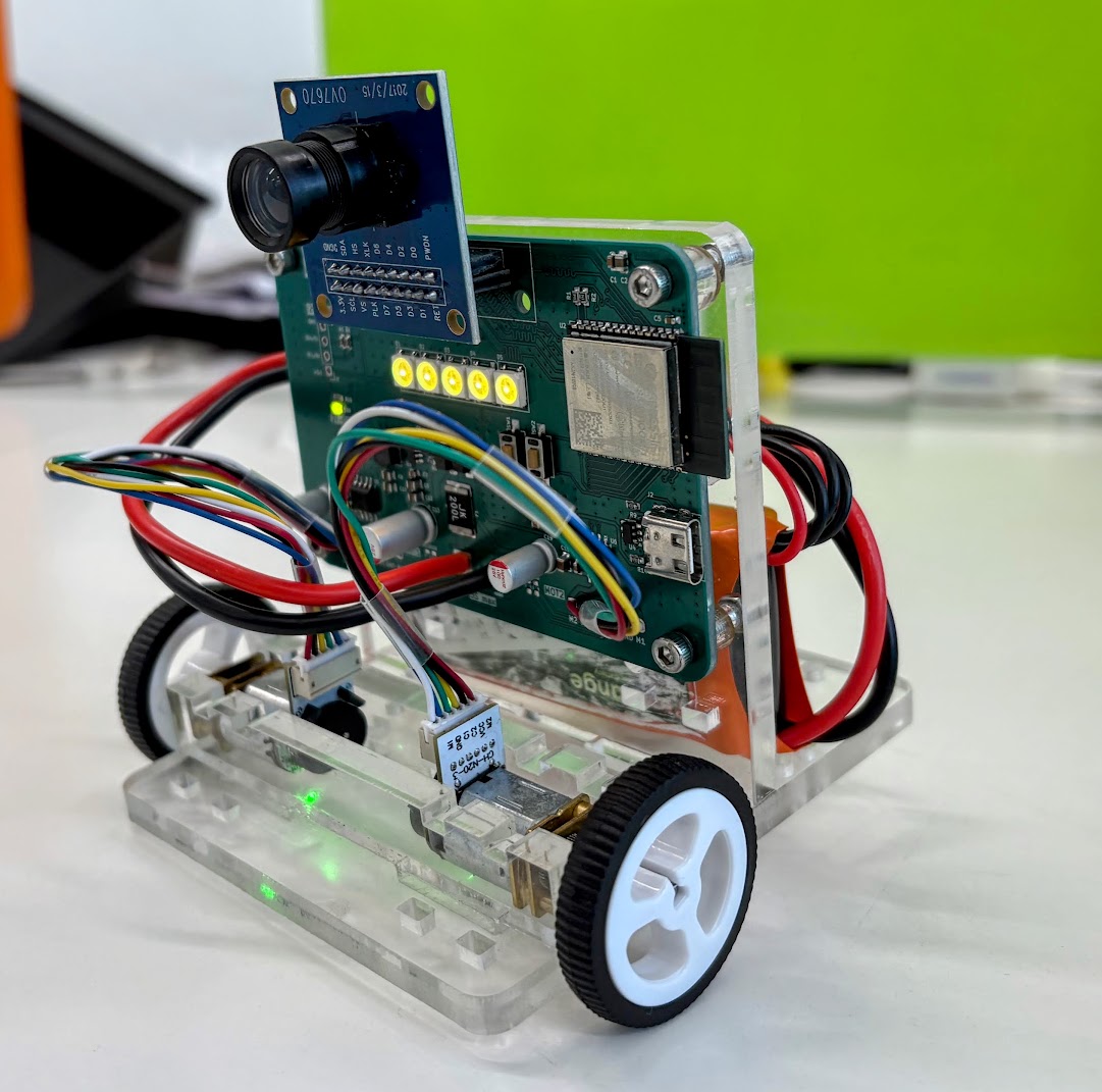
board_bringup/ — Arduino ESP32-S3 firmware for camera streaming over Wi-Fi and testing motors, quadrature encoders, and LEDs.camRover_pcb/camRover_pcb_v1_1/ — KiCad v1.1 project, hierarchical schematics, PCB layout, assembly files, stencil outputs, and release Gerbers/drill files.camrover_img.jpg — photo of the built rover.The sketch captures OV7670 RGB565 frames at QVGA (320 × 240), converts them to JPEG, and serves a browser-based test page. The page shows the live video and provides motor pulses, encoder tests, and RGB LED controls. Motor commands have a 2-second firmware watchdog.
Build tested with Arduino-ESP32 3.3.12.
Open board_bringup/board_bringup.ino in Arduino IDE. Keep sccb_ov7670_compat.cpp in the same sketch folder.
Install/select the Arduino-ESP32 3.3.12 board package.
Select ESP32S3 Dev Module and set:
| Setting | Value |
|---|---|
| Flash Size | 16MB (128Mb) |
| PSRAM | OPI PSRAM |
| USB CDC On Boot | Enabled |
Connect the ESP32-S3 board over USB, select its port, then compile and upload.
Open Serial Monitor at 115200 baud. After Wi-Fi connects, open the printed IP address in a browser.
Before uploading, set WIFI_SSID and WIFI_PASSWORD near the top of board_bringup.ino to your 2.4 GHz Wi-Fi credentials. The defaults in the sketch are local development settings; replace them for your network. The rover and browser must be on the same network. If Wi-Fi does not connect, motor and LED serial commands remain available.
Camera orientation and left-edge crop can be adjusted with CAMERA_ROTATION (0, 90, 180, or 270) and CAMERA_CROP_LEFT in the sketch.
The web page provides:
Serial commands at 115200 baud:
| Command | Action |
|---|---|
m <left> <right> | Drive motors with values from -255 to 255 (1-second timeout). |
s | Stop motors. |
l <r> <g> <b> | Set all five LEDs; each color value is 0–255. |
e | Print encoder counts. |
| Function | ESP32-S3 GPIO |
|---|---|
| OV7670 D0–D7 | 4, 8, 5, 9, 6, 10, 7, 11 |
| OV7670 XCLK / PCLK / VSYNC / HREF | 13 / 12 / 21 / 14 |
| OV7670 SIOD / SIOC | 16 / 17 |
| Motor 1 DRV8871 IN1 / IN2 | 18 / 15 |
| Motor 2 DRV8871 IN1 / IN2 | 42 / 47 |
| Motor 1 encoder A / B | 41 / 40 |
| Motor 2 encoder A / B | 2 / 1 |
| WS2812B chain DIN (5 LEDs) | 48 |
Open camRover_pcb/camRover_pcb_v1_1/camRover_pcb_v1_1.kicad_pro in KiCad. The project includes the main schematic and hierarchical sheets for the ESP32, motor drive, and power circuitry, plus the PCB layout and assembly bill of materials.
The CamRover_v1_1_Gerbers/ folder and CamRover_v1_1_Gerbers.zip contain the release copper, solder mask, paste, silkscreen, board outline, drill files, and drill maps for fabrication. Check the fabrication house’s layer and drill requirements before ordering.
| Qty | Value | Footprint | References |
|---|---|---|---|
| 11 | 10K_1%_0603 | Resistor_SMD:R_0603_1608Metric | R3, R4, R5, R6, R8, R10, R11, R15, R16, R17, R18 |
| 6 | 100n_0603_25V | Capacitor_SMD:C_0603_1608Metric | C3, C5, C6, C7, C16, C17 |
| 5 | WS2812B | iptif:LED_WS2812B_PLCC4_5.0x5.0mm_P3.2mm | D1, D2, D3, D4, D5 |
| 4 | 10u_0805_25V | Capacitor_SMD:C_0805_2012Metric | C9, C12, C14, C15 |
| 4 | MountingHole | MountingHole:MountingHole_3.2mm_M3 | H1, H2, H3, H4 |
| 3 | 1u_0603_25V | Capacitor_SMD:C_0603_1608Metric | C1, C4, C11 |
| 3 | 22u_0805_16V | Capacitor_SMD:C_0805_2012Metric | C2, C8, C10 |
| 3 | 33.2K_1%_0603 | Resistor_SMD:R_0603_1608Metric | R7, R12, R13 |
| 2 | 100uF/25V D5 | Capacitor_THT:CP_Radial_D5.0mm_P2.00mm | C18, C19 |
| 2 | 22R_0603 | Resistor_SMD:R_0603_1608Metric | R1, R2 |
| 2 | 4K7_0603 | Resistor_SMD:R_0603_1608Metric | R9, R14 |
| 2 | Conn_01x06 | iptif connectors:6pin_wireConn_2.54p | J4, J5 |
| 2 | DRV8871DDA | Package_SO:Texas_HTSOP-8-1EP_3.9x4.9mm_P1.27mm_EP2.95x4.9mm_Mask2.4x3.1mm_ThermalVias | U5, U6 |
| 2 | TSB008A2526A | Button_Switch_SMD:SW_SPST_CK_RS282G05A3 | SW1, SW2 |
| 1 | 220R@100M 0603 | Inductor_SMD:L_0603_1608Metric | FB1 |
| 1 | 3.3uH_SWPA5020 | Inductor_SMD:L_Sunlord_SWPA5020S | L1 |
| 1 | 470R_0603 | Resistor_SMD:R_0603_1608Metric | R19 |
| 1 | 470uF/25V D5 | Capacitor_THT:CP_Radial_D6.3mm_P2.50mm | C13 |
| 1 | Conn_01x02 | Connector_Wire:SolderWire-1.5sqmm_1x02_P7.8mm_D1.7mm_OD3.9mm | J3 |
| 1 | Conn_01x04 | Connector_PinHeader_2.54mm:PinHeader_1x04_P2.54mm_Vertical | J1 |
| 1 | ESP32-S3-WROOM-1 | RF_Module:ESP32-S3-WROOM-1 | U2 |
| 1 | LED | LED_SMD:LED_0805_2012Metric | D8 |
| 1 | OV7670 | iptif:ov7670_dipModule | U1 |
| 1 | Polyfuse - SMD200F/24-2920-2 | Fuse:Fuse_2920_7451Metric | F1 |
| 1 | SMAJ13CA | Diode_SMD:D_SMA | D6 |
| 1 | SRV05-4 | Package_TO_SOT_SMD:SOT-23-6 | U4 |
| 1 | SS34_SMA | Diode_SMD:D_SMA | D7 |
| 1 | TPS562201DDCR | Package_TO_SOT_SMD:SOT-23-6 | U3 |
| 1 | USB_C_Receptacle_USB2.0_16P | iptif:USB_C_Receptacle_U263-163N-4WS1735-XKB | J2 |
It measures 88 × 60 mm and has 2 copper layers, 1.6 mm thick.
66 parts, built around the ESP32-S3-WROOM-1-N8, DRV8871DDA, SRV05-4 and WS2812B. The full list of its parts is on this page, with links to each part's symbol and footprint where PCBKit's library has them.
From the aravindjayan/CamRover repository on GitHub, at the commit this page was made from: the board is camRover_pcb/camRover_pcb_v1_1/camRover_pcb_v1_1.kicad_pcb and its schematic camRover_pcb/camRover_pcb_v1_1/camRover_pcb_v1_1.kicad_sch. PCBKit opens the board in the browser, with nothing to install.
Its repository states no licence, so its author keeps all rights: ask aravindjayan before reusing the design.
86kkd/millionBoard
Amazing 500million sensor enetric skateboard use body center of gravity to control !!!

CyberSaiyanIT/why2025-badge
Cyber Saiyan community has designed and developed a special gadget for WHY2025. The badge was designed to recall the dragon spheres, and is an updated version of RomHack Camp 2022 badge, both in term of design and…


Omar-Magdy0/ReflowMate
To start small , grow big. current focus is mainly on providing : Digital Soldering iron support Hot air gun support 3d printable Accessories


petnica-rac-seminari/BCD-0o27-Tetris
The BalcCon Cyberdeck 0o27 (BCD-0o27) comes with a development framework that makes it easier to add functionality to the cyberdeck.

BYU-I-eBadge/e-badge
A hackable eBadge platform for students — a customizable, programmable electronics badge designed for hands-on learning and creative exploration throughout their academic journey.