2 layers10.7 × 20.8 mm

 araobp/can-bus12
CAN adapter to UART
Adapter is an open-source printed circuit board by araobp, from the araobp/can-bus repository on GitHub, published under the GPL-3.0 licence. It is a 2-layer board of 47.6 × 36.8 mm with 30 parts on 36 nets, routed with 196 tracks and 17 vias.
It is built around the PIC16F18326-I/P, MCP2561-E/P and MCP2515-I/P. Its parts include 7 connectors, 5 capacitors, 4 resistors, 4 ICs and 2 diodes. It belongs with the interfaces and adapters and home automation and IoT boards and the PIC boards of this library.


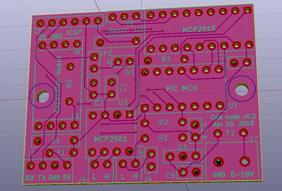
Printed circuit design for CAN node
(I have not tested the printed circuit board yet, because I have been too busy in other priority works)
I want to develop very cheap and low power sensor/actuator network with electronic parts sold in Akizuki-Denshi, Tokyo.
Most of parts I use are DIP.
I pursue seamless communications between CAN-bus and MQTT-bus:
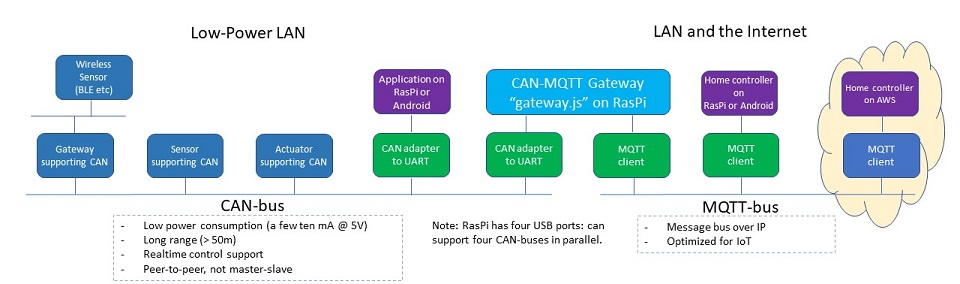
The CAN node consists of one base board and one expansion board.
See this page for expansion boards: EXPANSION BOARDS.
| Parameter | Value | Note |
|---|---|---|
| PIC16F1 MCU clock | 32MHz(Internal OSC 8MHz * 4 PLL) | |
| UART baud rate | 9600bps (fixed) | Full-duplex wire-rate is not supported |
| SPI clock | 2MHz (fixed) | |
| CAN speed | Max. 250kHz (default 125kHz) | |
| Oscillator for CAN controller | 8MHz (ceramic) | Murata Ceralock |
| Expansion board | 8 pins connected to PIC MCU |
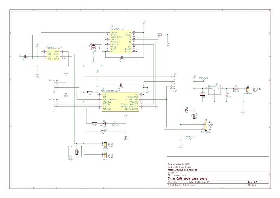
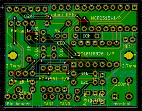
This implementation supports CAN Standard Frame only (does not support Extended Frame). For home networking, 11bit Standard Identifier suffices.
=> FORMAT
This implementation supports CAN adapter functionality for PC and Android.
/// UART2CAN HELP (version 0.11  March 19, 2018) ///
[Set standard identifier] @i<standard identifier>
[Set output mode] {debug: @vd, verbose: @vv, normal: @vn}
[Enable operation mode] {loopback: @ol, normal: @on}
     with SID: @ols or @ons
[Set mask] @m<n><mask(SID10 ~ SID0)>
[Set filter] @f<n><filter(SID10 ~ SID0)>
[Set baud rate] @b<bpr>
[Abort all pending transmissions] @a
[Dump masks and filters] @F
[Dump registers] @D
[Send message] <message>
[Send message beginning with '@' character] @<@message>
[Receive message] <message> will be output
[Show this help]: @h
For example, to receive messages with SID 5, 10 and 15, set masks and filters to the CAN adapter as follows:
@m02047  --> RXM0 0b11111111111
@f05     --> RXF0 0b00000000101 (SID 5 message to RXB0)
@f110    --> RXF1 0b00000001010 (SID 10 message to RXB0)
@m12047  --> RXM1 0b11111111111
@f215    --> RXF2 0b00000001111 (SID 15 message to RXB1)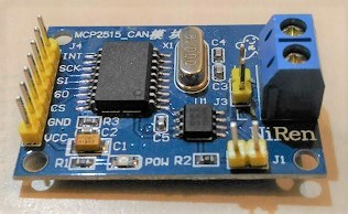
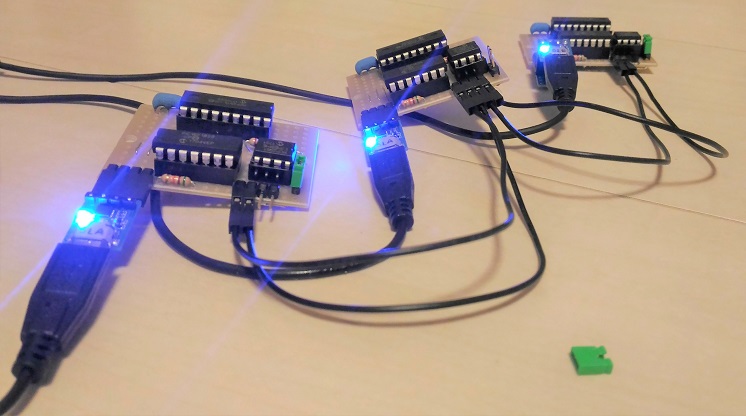
At first, I use this universal board to make a prototype of the CAN adaptor:
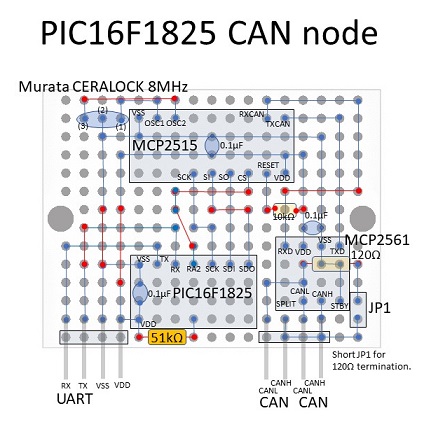
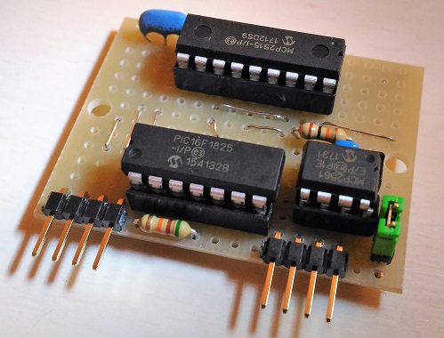
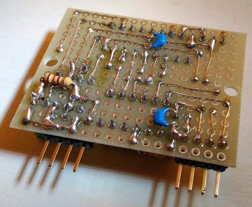
I have finished the first prototype (Marth 25-27, 2018). I have made three boards, and it took eight hours.
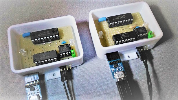
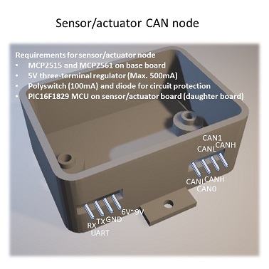
3D printed enclosure for CAN node
| Qty | Value | Footprint | References |
|---|---|---|---|
| 4 | 0.1u | can-bus:Capacitor_2.54mm | C1, C2, C3, C5 |
| 2 | 250mA | can-bus:Polyswitch_Tyco | F1, F2 |
| 2 | Jumper | can-bus:Jumper_1x2 | JP1, JP2 |
| 2 | Pin socket | can-bus:PinSocket_1x4 | J2, J3 |
| 1 | 10k | can-bus:Resistor_FaithfulLink_CF25 | R3 |
| 1 | 120 | can-bus:Resistor_FaithfulLink_CF25 | R1 |
| 1 | 1A | can-bus:Diode | D1 |
| 1 | 1k | can-bus:Resistor_FaithfulLink_CF25 | R5 |
| 1 | 47u | can-bus:Capacitor_2.54mm | C4 |
| 1 | 51k | can-bus:Resistor_FaithfulLink_CF25 | R2 |
| 1 | CAN0 | can-bus:PinHeader_1x2_L_Shape | J4 |
| 1 | CAN1 | can-bus:PinHeader_1x2_L_Shape | J5 |
| 1 | Ceralock 8MHz | can-bus:Ceralock_Murata | Y1 |
| 1 | ICSP | can-bus:PinSocket_1x6 | J6 |
| 1 | LED | can-bus:Led | D3 |
| 1 | MCP2515-I/P | can-bus:IC_socket_18pins | U3 |
| 1 | MCP2561-E/P | can-bus:IC_Socket_8pins | U2 |
| 1 | PIC16f18326-I/P | can-bus:IC_socket_14pins | U1 |
| 1 | Pin header | can-bus:PinHeader_1x4_L_Shape | J1 |
| 1 | SW | can-bus:TactileSwitch | Reset |
| 1 | regulator | can-bus:TA48M05F | U4 |
| 1 | terminal | can-bus:Terminal_PhoenixContact_2P | J7 |
The 28 most common of 30 parts.

mocketech/EmoGo
A Go game system that conveys the state of Go stones through facial expressions


xerootg/CAN-CCD_bus
Implements a CAN translator to CCD via a Intersil CDP68HC68S1

DashSight/Pine64-Mezzanine-Card
A PineA64 mezzanine card for adding support to communicate with a vehicle's OBD2 port, obtain GPS location and determine acceleration, designed in KiCAD

kevinkrieger/CAN
CAN repository containing my CAN project, kicad files, firmware, datasheets, references, etc.


Gonke0606/Personal_production_circuit
This repository is for my personal production of circuit.

It measures 47.6 × 36.8 mm and has 2 copper layers, 1.6 mm thick.
30 parts, built around the PIC16F18326-I/P, MCP2561-E/P and MCP2515-I/P. The full list of its parts is on this page, with links to each part's symbol and footprint where PCBKit's library has them.
From the araobp/can-bus repository on GitHub, at the commit this page was made from: the board is KiCAD/circuit/adapter.kicad_pcb. PCBKit opens the board in the browser, with nothing to install.
Its repository publishes it under the GPL-3.0 licence: you may reuse it on that licence's terms (keep the author's notice, and for a copyleft licence share your changes alike).