
4 layers92.1 × 62.8 mm
Motor controller
mohamed-belal-10/can-motor-controller-node
CAN-connected closed-loop DC motor controller node — KiCad hardware (STM32F103, DRV8874, SN65HVD230) with an AS5600 encoder sub-PCB
55 partsMIT

 aramder/orc
Open replacement controller board for surplus Motorola PMUN1046A relay boxes: ESP32-C3, CANopen control, 10 x 15 A channels. Independent project, not affiliated with Motorola Solutions.
Orc is an open-source printed circuit board by aramder, from the aramder/orc repository on GitHub. It is a 2-layer board of 95 × 82 mm with 85 parts on 103 nets, routed with 652 tracks and 160 vias.
It is built around the SN65HVD230D, ADUM1250ARZ-RL7 and AMS1117-3.3, with the PCA9555PW, SS34 and AO3401A among its other parts. Its parts include 21 resistors, 20 transistors, 15 capacitors, 12 diodes and 7 ICs. It belongs with the home automation and IoT and interfaces and adapters boards and the ESP32 and RISC-V boards of this library.




A replacement controller board for surplus Motorola PMUN1046A relay boxes — same relays and enclosure; open CAN control over plain terminal blocks instead of the proprietary wired link to the radio.
Independent open-source project. Not affiliated with, endorsed by, or connected to Motorola Solutions, Inc. — see TRADEMARKS.md.
Safety: this switches high-current DC in a vehicle. It is not safety qualified and must not be used for safety-critical functions. Read DISCLAIMER.md before building anything.
The PMUN1046A Universal Relay Controller (URC) is a sealed 12 V automotive relay box — ten relay outputs at 15 A each, per-channel fusing, and a busbar power input rated for up to two cables at 60 A each (Motorola's install manual), in a trunnion-mounted weatherproof chassis. Power goes straight to the busbar through cable glands — no special harness needed on the input side. Surplus units are common and cheap. Everything about it is desirable except that it only takes commands from a Motorola APX radio over a proprietary GCAI/USB link.
ORC replaces the controller board outright and makes the box a general-purpose, openly-controlled ten-channel power distribution module. ORC stands for Open Relay Controller.
ORC does not implement, emulate, or interoperate with the GCAI link. The controller board is an independent design that replaces the donor unit's controller board entirely; control is plain CAN or USB.
Motorola's URC ships as part of the APX mobile radio ecosystem — a sealed relay box meant to switch scene lighting, sirens, and other accessory loads from the radio head. The relay board and chassis are generic 12 V automotive gear; only the controller board and its proprietary GCAI/USB command link to the radio are Motorola-specific. The relay board is entirely passive (relays, fuses, terminal blocks, busbar — no drivers or regulator of its own); a small internal harness carries switched 9 V coil drive between it and the controller board. Power input has no special harness at all — it lands straight on the busbar through the enclosure's cable glands. ORC keeps the relay board and chassis, and replaces the controller board and its proprietary radio link with plain CAN over terminal blocks — no proprietary connector anywhere in this design.
|
Inherited from the donor unit
|
Rebuilt on the new controller board
|
Category-wise this is a PDM (power distribution module) — the sPOD / Switch-Pros class of device — with an open CAN control interface instead of a proprietary wired link to the radio.
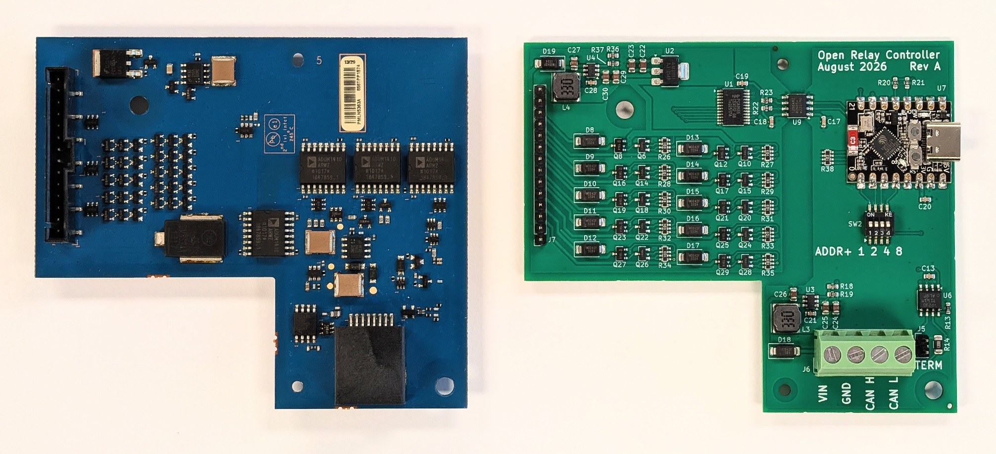
ORC Rev A (green, right) and the OEM control PCB it replaces (blue, left).
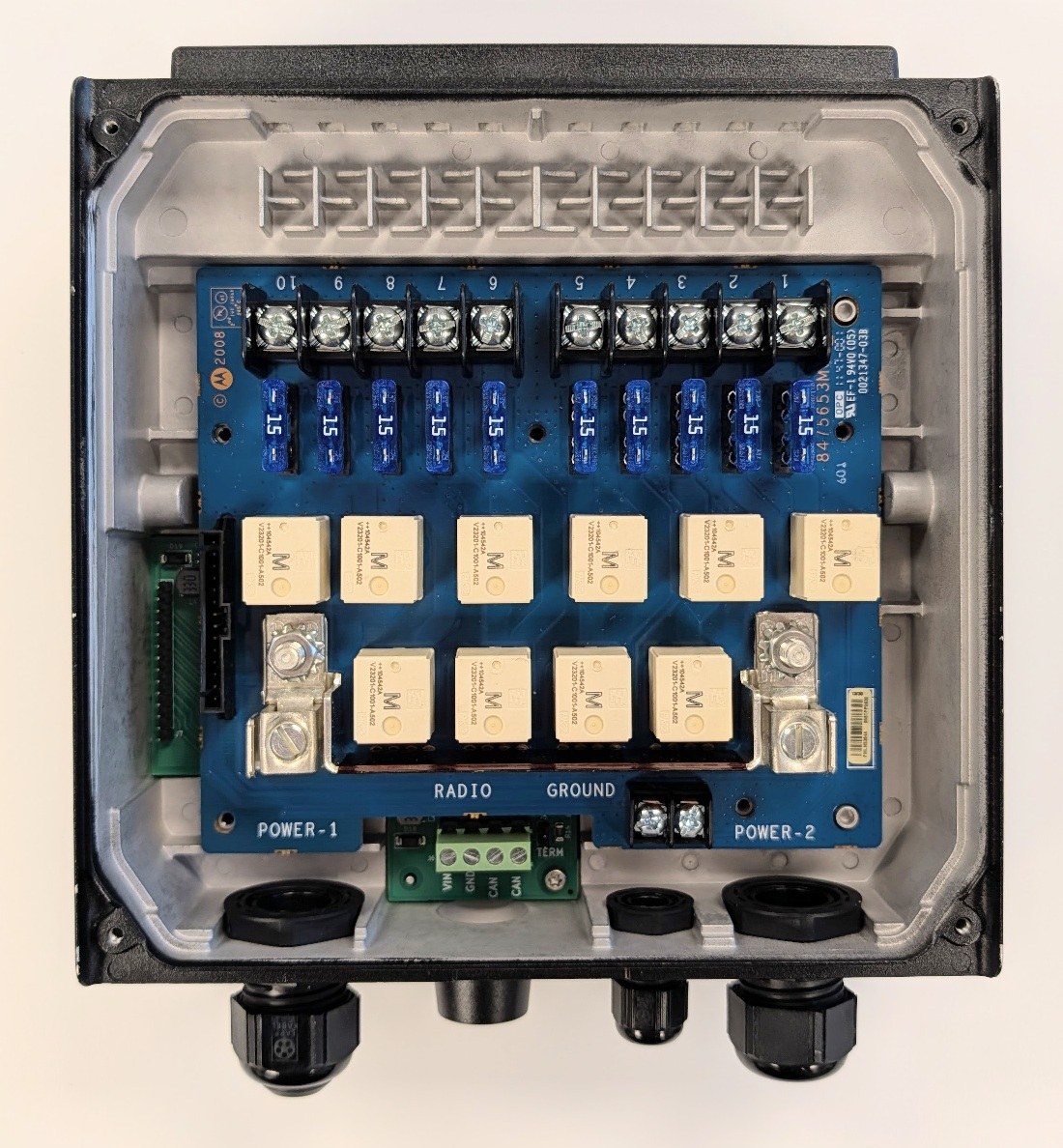
ORC Rev A installed in the donor enclosure, alongside the OEM relay board that stays.
Full writeup, build story, and more photos: Open Relay Controller for the Motorola PMUN1046A.
One repo for design inputs, hardware, and firmware — no split-repo overhead for a project this size:
| Path | Contents | Status |
|---|---|---|
docs/ | Design inputs, specs, architecture decisions | Active |
hardware/ | KiCad project — schematic, PCB, BOM | Schematic captured, boards fabricated, populated, and bring-up verified on real hardware |
firmware/ | PlatformIO / Arduino firmware | canopen_app is real application firmware (CAN + USB relay control), verified on real hardware |
tools/ | Host-side CAN/USB bench test scripts | Used against real hardware |
Different parts of the repo carry different licenses. Full texts are in LICENSES/; each directory also carries its own LICENSE file.
| Path | License |
|---|---|
hardware/ | CERN-OHL-W-2.0 |
firmware/, tools/ | Apache-2.0 |
docs/ | CC-BY-4.0 |
Hardware and software are licensed separately because they are separate works: under CERN-OHL's own definitions the ESP32-C3 is an Available Component, so a hardware license on the board does not reach the code running on it. See NOTICE for the summary and TRADEMARKS.md for trademark and affiliation.
Real-hardware bring-up complete. Boards were sent to fab 2026-08-02, came back populated, and have been bench-tested since 2026-08-10: the PCA9555/I2C-isolator chain, the full 10-channel relay-driver mapping, and the CAN (RPDO1/TPDO1/TPDO2/Heartbeat) and USB control paths have all been exercised on real hardware. Five real firmware bugs were found and fixed along the way — BUG-001 through BUG-005, see docs/features/LOG.md for the full history — the last of which (a liveness stall under an absent/unpowered PCA9555) was verified on real hardware 2026-09-04. One real mechanical fault (a harness connector shorting against the enclosure chassis) was also found and fixed on the bench — see docs/circuit-draft.md for the follow-up enclosure-clearance item.
No further active development is planned barring a new bug. A couple of feature requests (FR-003, FR-005) remain open in the backlog but aren't being actively pursued right now.
Working conventions for part selection, asset verification, and check gates: docs/hardware-workflow.md. Bench test tooling for talking to a real board over CAN/USB from a PC: tools/.
| Qty | Value | Footprint | References |
|---|---|---|---|
| 11 | 10k 5% | Resistor_SMD:R_Array_Concave_4x0603 | R26, R27, R28, R29, R30, R31, R32, R33, R34, R35, R38 |
| 11 | SS34 | Diode_SMD:D_SMA | D8, D9, D10, D11, D12, D13, D14, D15, D16, D18, D19 |
| 10 | AO3401A | Package_TO_SOT_SMD:SOT-23 | Q8, Q12, Q16, Q17, Q19, Q21, Q23, Q25, Q27, Q29 |
| 10 | MMBT3904 | Package_TO_SOT_SMD:SOT-23 | Q6, Q10, Q14, Q15, Q18, Q20, Q22, Q24, Q26, Q28 |
| 8 | 10uF 50V | Capacitor_SMD:C_0805_2012Metric | C22, C23, C24, C25, C26, C27, C29, C30 |
| 7 | 100nF 50V | Capacitor_SMD:C_0603_1608Metric | C13, C17, C18, C19, C20, C21, C28 |
| 4 | 10k 1% | Resistor_SMD:R_0603_1608Metric | R20, R21, R22, R23 |
| 2 | 2.5mm NP | MountingHole:MountingHole_2.5mm | MNT2, MNT4 |
| 2 | 33uH | Inductor_SMD:L_Chilisin_BWVS00606045 | L3, L4 |
| 2 | 4mm NP | MountingHole:MountingHole_4mm | MNT1, MNT3 |
| 2 | LMR50410 | Package_TO_SOT_SMD:SOT-23-6 | U3, U4 |
| 1 | 01x02 | Connector_PinHeader_2.54mm:PinHeader_1x02_P2.54mm_Vertical | J5 |
| 1 | 10k 0.1% | Resistor_SMD:R_0603_1608Metric | R13 |
| 1 | 10x SS34 | Diode_SMD:D_SMA | D17 |
| 1 | 120 1% | Resistor_SMD:R_1206_3216Metric | R14 |
| 1 | 2.7k 1% | Resistor_SMD:R_0603_1608Metric | R19 |
| 1 | 24k 1% | Resistor_SMD:R_0603_1608Metric | R36 |
| 1 | 3k 1% | Resistor_SMD:R_0603_1608Metric | R37 |
| 1 | 5.08mm Screw Terminal | Connector_Samtec_HPM_THT:Samtec_HPM-04-01-x-S_Straight_1x04_Pitch5.08mm | J6 |
| 1 | 6.2k 1% | Resistor_SMD:R_0603_1608Metric | R18 |
| 1 | ADuM1250ARZ-RL7 | Package_SO:SOIC-8_3.9x4.9mm_P1.27mm | U9 |
| 1 | AMS1117-3.3 | Package_TO_SOT_SMD:SOT-223-3_TabPin2 | U2 |
| 1 | ESP32-C3-SuperMini | AramLib:ESP32-C3-SuperMini | U7 |
| 1 | Harness, 14-pos 0.1in THT | Connector_PinSocket_2.54mm:PinSocket_1x14_P2.54mm_Vertical | J7 |
| 1 | PCA9555PW | Package_SO:TSSOP-24_4.4x7.8mm_P0.65mm | U1 |
| 1 | SN65HVD230 | Package_SO:SOIC-8_3.9x4.9mm_P1.27mm | U6 |
| 1 | SW_DIP_x04 | Package_SO:SOIC-8_5.3x5.3mm_P1.27mm | SW2 |
It measures 95 × 82 mm and has 2 copper layers, 1.6 mm thick.
85 parts, built around the SN65HVD230D, ADUM1250ARZ-RL7, AMS1117-3.3 and PCA9555PW. The full list of its parts is on this page, with links to each part's symbol and footprint where PCBKit's library has them.
From the aramder/orc repository on GitHub, at the commit this page was made from: the board is hardware/orc.kicad_pcb and its schematic hardware/communications.kicad_sch. PCBKit opens the board in the browser, with nothing to install.
Its repository states no licence, so its author keeps all rights: ask aramder before reusing the design.
mohamed-belal-10/can-motor-controller-node
CAN-connected closed-loop DC motor controller node — KiCad hardware (STM32F103, DRV8874, SN65HVD230) with an AS5600 encoder sub-PCB


michpro/mikroBUS
Collection of add-on boards in mikroBUS™ standard

NuttyShell/NuttyBadge
NuttyBadge: A NuttyShell crafted multi-tool. Opensourced Hardawre and Software

xmyoot/esp32-media-carrier
ESP32 multimedia carrier board with 7–24 V DC buck regulator, 3.2 W Class-D I2S audio amp, WS2812 LED ring driver, and SPI TFT display header


lansalot/AOG_Dev
Like AgOpenGPS but not. This version is constantly under development.
