
2 layers86 × 90 mm

 ar216-2355/Line_follower_robot
Line follower robot is an open-source printed circuit board by ar216-2355, from the ar216-2355/Line_follower_robot repository on GitHub. It is a 2-layer board of 100 × 100 mm with 58 parts on 60 nets, routed with 354 tracks and 134 vias.
It is built around the ESP-WROOM-02U. Its parts include 18 resistors, 8 capacitors, 6 ICs, 6 diodes and 6 connectors. It belongs with the robots and motor control boards of this library.
ライントレーサー用基板
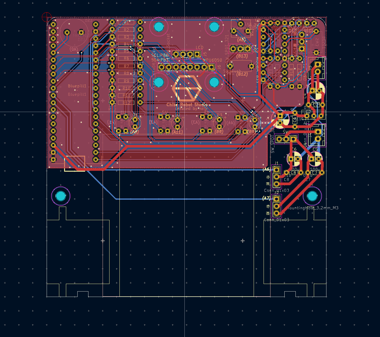
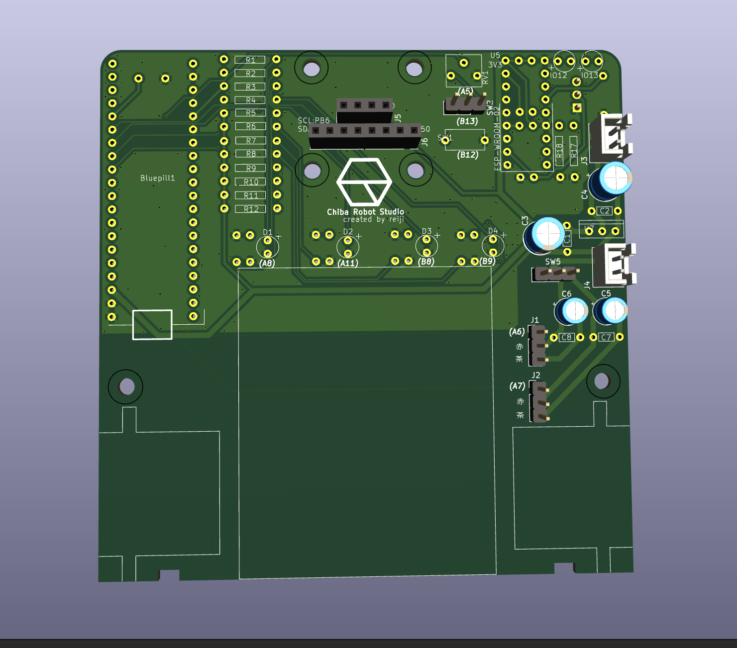
| Qty | Value | Footprint | References |
|---|---|---|---|
| 8 | 10k | Line_follower_robot:resistor_10mm | R5, R6, R7, R8, R13, R14, R15, R16 |
| 6 | 440 | Line_follower_robot:resistor_10mm | R1, R2, R3, R4, R17, R18 |
| 6 | LED | Line_follower_robot:LED_2.54mm | D1, D2, D3, D4, IO12, IO13 |
| 4 | 0.1u | Line_follower_robot:capa_5.1 | C1, C2, C7, C8 |
| 4 | 100 | Line_follower_robot:resistor_10mm | R9, R10, R11, R12 |
| 4 | BPR-105F | Line_follower_robot:photo_refrector | U1, U2, U3, U4 |
| 3 | SW_SPDT_321 | Connector_PinHeader_2.54mm:PinHeader_1x03_P2.54mm_Vertical | SW2, SW4, SW5 |
| 2 | 100u | Capacitor_THT:CP_Radial_D5.0mm_P2.50mm | C5, C6 |
| 2 | 10u | Capacitor_THT:CP_Radial_D6.3mm_P2.50mm | C3, C4 |
| 2 | Conn_01x02 | Connector_JST:JST_XH_B2B-XH-A_1x02_P2.50mm_Vertical | J3, J4 |
| 2 | Conn_01x03 | Connector_PinHeader_2.54mm:PinHeader_1x03_P2.54mm_Vertical | J1, J2 |
| 2 | SW_Push | Line_follower_robot:tact_switch | SW1, SW3 |
| 1 | AZ1117-3.3 | Line_follower_robot:3v3regulator | U7 |
| 1 | Conn_01x04_Socket | Connector_PinSocket_2.54mm:PinSocket_1x04_P2.54mm_Vertical | J5 |
| 1 | Conn_01x08_Socket | Connector_PinSocket_2.54mm:PinSocket_1x08_P2.54mm_Vertical | J6 |
| 1 | R_Potentiometer | Line_follower_robot:Potentionmeter | RV1 |
| 1 | Speaker | Line_follower_robot:my_speaker | LS1 |
| 1 | esp_wroom_02 | Line_follower_robot:esp32_wroom_02 | U5 |
| 1 | ~ | Line_follower_robot:blue pill | Bluepill1 |
The 52 most common of 58 parts.

generationmake/Stromwaechter_PCB
PCB with current sensors for 12 V battery systems


zynthian/zynthian-hw
Zynthian hardware stuff: PCBs, schemes, parts specifications, pin assignment, ...


Hack-a-Day/2025-Communicator_Badge
The 2025 Hackaday Supercon RF Communicator Badge
It measures 100 × 100 mm and has 2 copper layers, 1.6 mm thick.
58 parts, built around the ESP-WROOM-02U. The full list of its parts is on this page, with links to each part's symbol and footprint where PCBKit's library has them.
From the ar216-2355/Line_follower_robot repository on GitHub, at the commit this page was made from: the board is Line_follower_robot.kicad_pcb and its schematic Line_follower_robot.kicad_sch. PCBKit opens the board in the browser, with nothing to install.
Its repository states no licence, so its author keeps all rights: ask ar216-2355 before reusing the design.