
2 layers100 × 87.5 mm

 APrymas/Capacitance-Frequency-Meter1
ESP32-C3-Zero capacitance and frequency meter featuring auto-ranging, TARE compensation, custom PCB and complete KiCad project files.
Miernik płytka is an open-source printed circuit board by APrymas, from the APrymas/Capacitance-Frequency-Meter repository on GitHub, published under the MIT licence. It is a 2-layer board of 127.1 × 45 mm with 23 parts on 32 nets, routed with 128 tracks and 0 vias.
It is built around the LT1016CD. Its parts include 14 resistors, 3 connectors, 2 ICs, 2 switches and 1 capacitor.
🇵🇱 Polski | 🇬🇧 English
ESP32-C3-Zero Capacitance & Frequency Meter to kompaktowy, otwartoźródłowy miernik pojemności oraz częstotliwości oparty na mikrokontrolerze ESP32-C3-Zero.
Projekt został stworzony jako niedrogie i praktyczne narzędzie pomiarowe do pracy z elektroniką. Urządzenie pozwala mierzyć pojemność kondensatorów od około 33 pF oraz częstotliwość sygnałów cyfrowych do 250 kHz.
Repozytorium zawiera zarówno część programową, jak i sprzętową projektu: firmware, schemat oraz projekt PCB wykonany w KiCad 9.0.
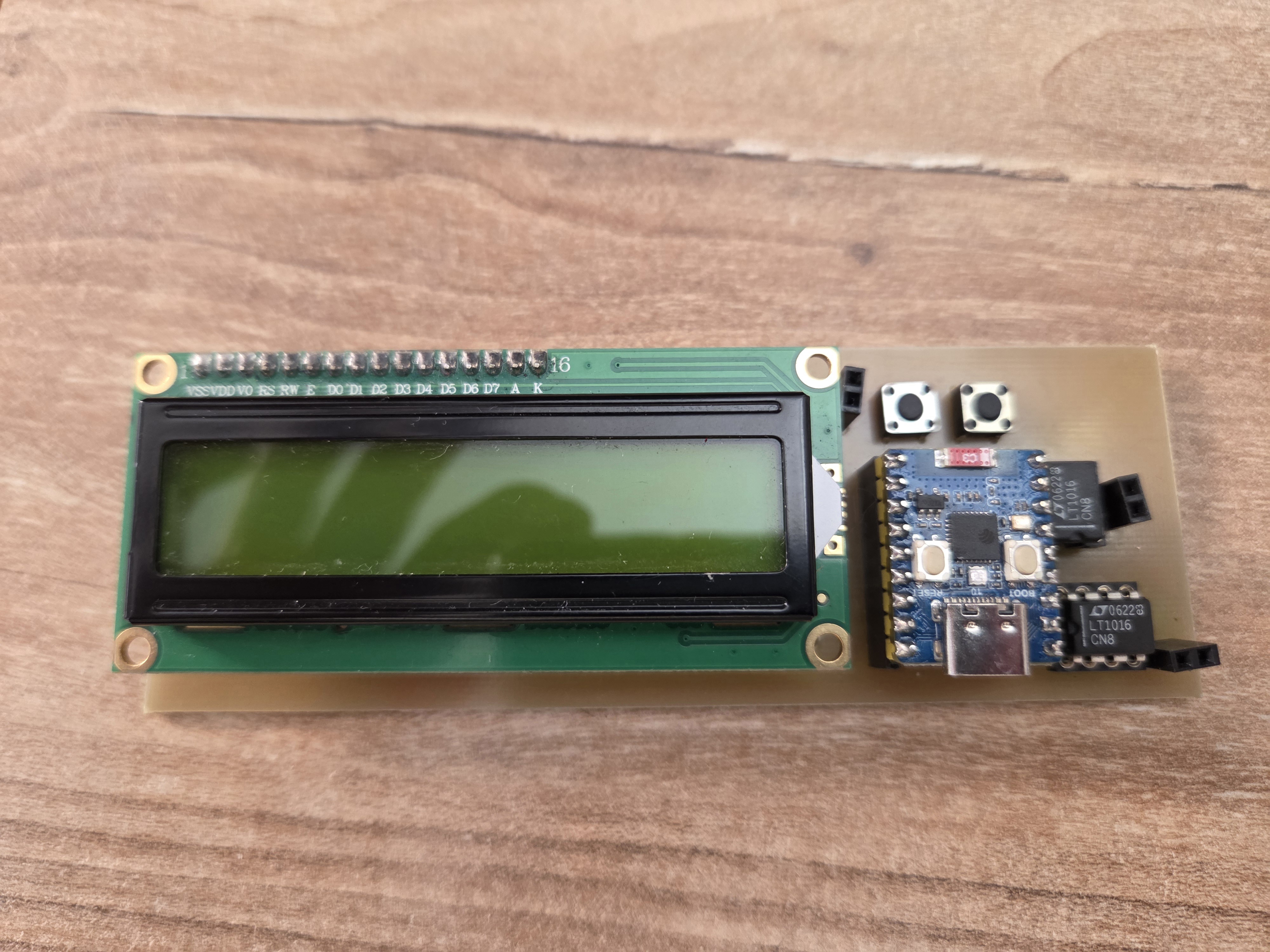
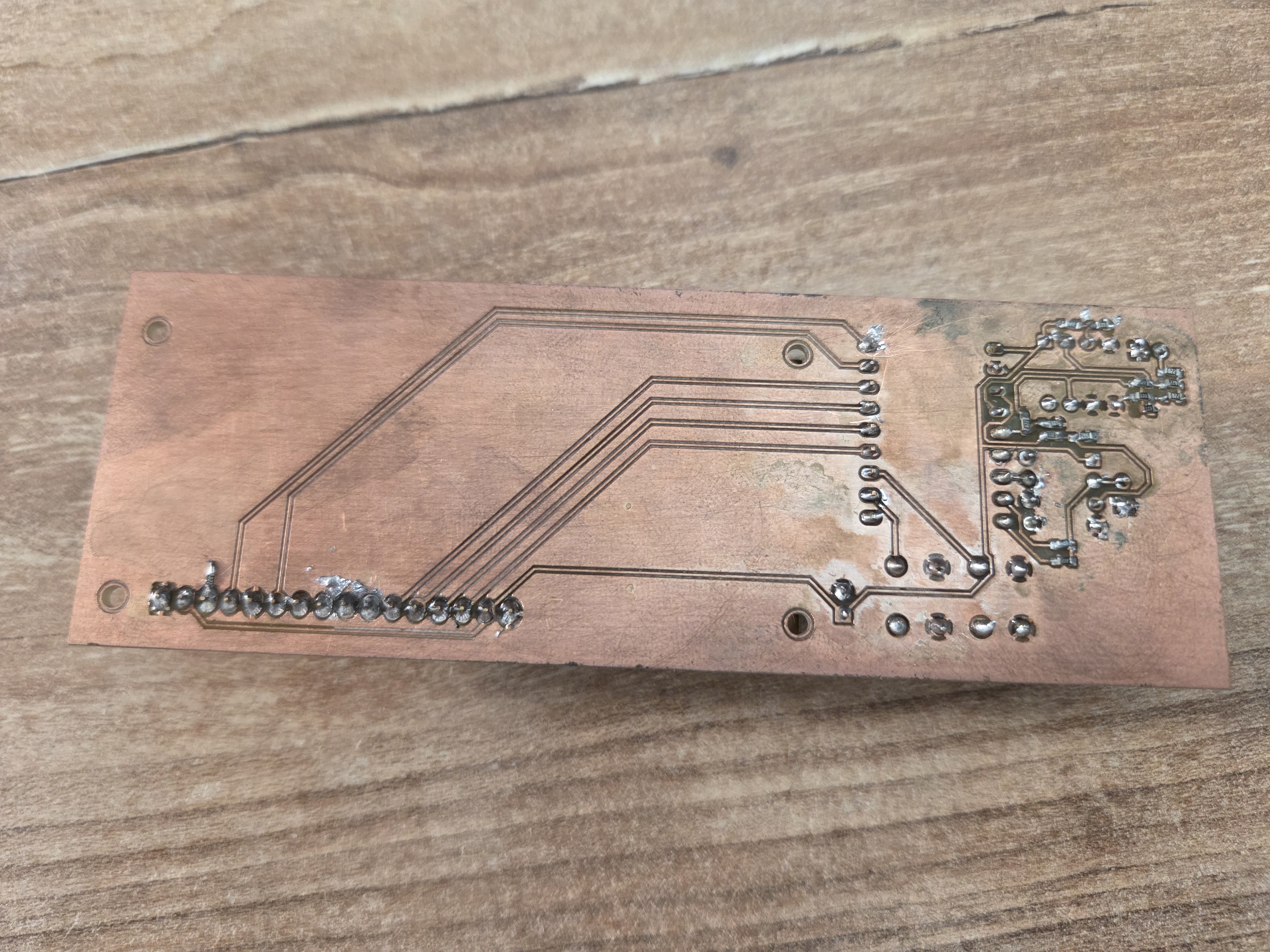
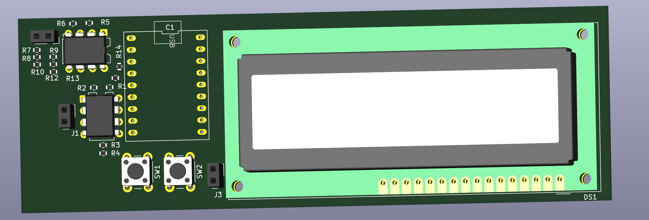
Pomiar pojemności realizowany jest poprzez pomiar czasu ładowania kondensatora przez rezystor o znanej wartości.
Mikrokontroler ESP32-C3-Zero mierzy czas potrzebny do osiągnięcia określonego progu napięcia wykrywanego przez szybki komparator LT1016.
W projekcie zastosowano dwa zakresy pomiarowe:
| Zakres | Rezystor |
|---|---|
| Małe pojemności | 100 kΩ |
| Duże pojemności | 2.2 kΩ |
Przełączanie zakresu odbywa się automatycznie w programie.
Sygnał wejściowy podawany jest bezpośrednio na wejście mikrokontrolera ESP32-C3.
Każde narastające zbocze sygnału wywołuje przerwanie sprzętowe. Program zlicza impulsy w określonym czasie, a następnie przelicza wynik na częstotliwość.
Obsługiwane jednostki:
| Element | Opis |
|---|---|
| ESP32-C3-Zero | Główny mikrokontroler |
| LT1016 | Szybki komparator napięcia |
| Rezystor 100 kΩ | Zakres małych pojemności |
| Rezystor 2.2 kΩ | Zakres dużych pojemności |
| Przyciski TACT | Sterowanie urządzeniem |
| Złącza goldpin | Wejścia pomiarowe |
Repozytorium zawiera:
.
├── firmware/
│   └── cap&frq_meter.ino
│
├── hardware/
│   ├── cap&frq_meter.kicad_sch
│   └── cap&frq_meter.kicad_pcb
│
├── images/
│
├── README.md
└── LICENSEFirmware został napisany w języku C++ z wykorzystaniem środowiska Arduino IDE oraz rdzenia Arduino Core for ESP32.
Wykorzystane biblioteki:
ESP32-C3-Zero Capacitance & Frequency Meter is a compact open-source capacitance and frequency meter based on the ESP32-C3-Zero microcontroller.
The project was created as a low-cost and practical measurement tool for electronics work. The device can measure capacitor values starting from approximately 33 pF and digital signal frequencies up to 250 kHz.
This repository contains both the software and hardware parts of the project: firmware, schematic and PCB design created in KiCad 9.0.
Capacitance is measured by monitoring the charging time of a capacitor through a resistor with a known value.
The ESP32-C3-Zero measures the time required to reach a voltage threshold detected by the high-speed LT1016 comparator.
Two measurement ranges are used:
| Range | Resistor |
|---|---|
| Small capacitances | 100 kΩ |
| Large capacitances | 2.2 kΩ |
Range switching is performed automatically in firmware.
The input signal is connected directly to an ESP32-C3 input pin.
Each rising edge of the signal generates a hardware interrupt. The firmware counts pulses over a defined time period and converts the result into frequency.
Supported units:
| Component | Description |
|---|---|
| ESP32-C3-Zero | Main microcontroller |
| LT1016 | High-speed voltage comparator |
| 100 kΩ resistor | Small capacitance range |
| 2.2 kΩ resistor | Large capacitance range |
| TACT switches | User controls |
| Pin headers | Measurement inputs |
This repository contains:
.
├── firmware/
│   └── cap&frq_meter.ino
│
├── hardware/
│   ├── cap&frq_meter.kicad_sch
│   └── cap&frq_meter.kicad_pcb
│
├── images/
│
├── README.md
└── LICENSEThe firmware is written in C++ using Arduino IDE and Arduino Core for ESP32.
Libraries used:
Released under the MIT License.
Feel free to use, modify and improve the project.
| Qty | Value | Footprint | References |
|---|---|---|---|
| 4 | 8k2 | Resistor_SMD:R_0603_1608Metric_Pad0.98x0.95mm_HandSolder | R7, R8, R10, R13 |
| 2 | 220k | Resistor_SMD:R_0603_1608Metric_Pad0.98x0.95mm_HandSolder | R5, R9 |
| 2 | 580 | Resistor_SMD:R_0603_1608Metric_Pad0.98x0.95mm_HandSolder | R11, R12 |
| 2 | 68k | Resistor_SMD:R_0603_1608Metric_Pad0.98x0.95mm_HandSolder | R6, R14 |
| 2 | Conn_01x02_Socket | Connector_PinSocket_2.54mm:PinSocket_1x02_P2.54mm_Vertical | J1, J2 |
| 2 | LT1016 | Package_DIP:DIP-8_W7.62mm | U1, U2 |
| 2 | SW_DPST_x2 | Button_Switch_THT:SW_PUSH_6mm_H4.3mm | SW1, SW2 |
| 1 | 100k | Resistor_SMD:R_0603_1608Metric_Pad0.98x0.95mm_HandSolder | R3 |
| 1 | 2k2 | Resistor_SMD:R_0603_1608Metric_Pad0.98x0.95mm_HandSolder | R4 |
| 1 | 3k3 | Resistor_SMD:R_0603_1608Metric_Pad0.98x0.95mm_HandSolder | R1 |
| 1 | 5k6 | Resistor_SMD:R_0603_1608Metric_Pad0.98x0.95mm_HandSolder | R2 |
| 1 | Conn_01x02_Pin | Connector_PinSocket_2.54mm:PinSocket_1x02_P2.54mm_Vertical | J3 |
| 1 | WC1602A | Display:WC1602A | DS1 |
| 1 | ~ | ESP32:ESP32_C3_ZERO | C1 |
It measures 127.1 × 45 mm and has 2 copper layers, 1.6 mm thick.
23 parts, built around the LT1016CD. The full list of its parts is on this page, with links to each part's symbol and footprint where PCBKit's library has them.
From the APrymas/Capacitance-Frequency-Meter repository on GitHub, at the commit this page was made from: the board is hardware/KiCad 9.0/Miernik_płytka.kicad_pcb and its schematic hardware/KiCad 9.0/Miernik_f.kicad_sch. PCBKit opens the board in the browser, with nothing to install.
Its repository publishes it under the MIT licence: you may reuse it on that licence's terms (keep the author's notice, and for a copyleft licence share your changes alike).


G-Leonel-6/C2
En este repositorio se guardaran los archivos correspondientes al desarrollo de una fuente de alimentacion regulada


google/mozc-devices
Circuit diagrams and firmware source code for Gboard DIY keyboards


