2 layers28 × 65 mm
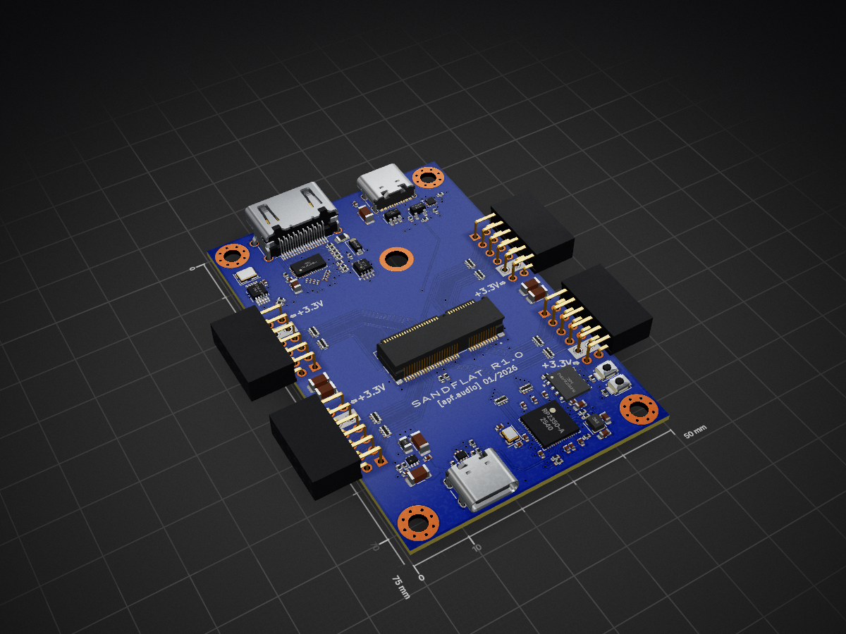
 apfaudio/sandflat4
Lower-cost DSP experimentation host for the SoldierCrab ECP5 SoM
Sandflat is an open-source printed circuit board by apfaudio, from the apfaudio/sandflat repository on GitHub, published under the CERN-OHL-S-2.0 licence. It is a 6-layer board of 50 × 75 mm with 113 parts on 221 nets, routed with 1,375 tracks and 169 vias.
It is built around the W25Q128JVPIQ, AP2161WG and PCA9306D, with the SI5351A-B-GT, USBLC6-2P6 and USBLC6-4SC6 among its other parts. Its parts include 37 capacitors, 32 resistors, 10 ICs, 8 connectors and 2 switches. It belongs with the computers and single-board computers and fPGA and programmable logic boards and the RP2350 boards of this library.


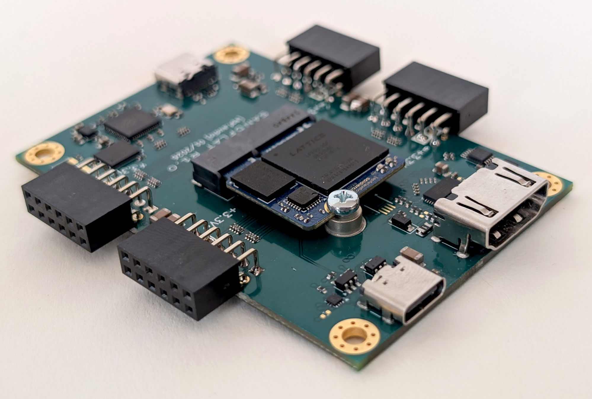
SandFlat is an open-hardware development board based on our SoldierCrab M.2 FPGA SoM. Its primary goal is similar to Tiliqua in that it aims to be a an audio and video DSP experimentation platform - however, compared to Tiliqua, SandFlat has less features, is a bare board, and can be manufactured much more cheaply (around $40-50 for both the SoM and SandFlat together in reasonable quantities). This makes a different set of tradeoffs to Tiliqua.
The main difference is that there are no audio CODECs or audio frontend on SandFlat. These can be added with PMODs on one of the 4 expansion connectors (e.g. our own eurorack-pmod). Crucially, no additional hardware is needed to play with audio DSP in hardware on SandFlat, as you can stream audio straight into / out of your computer/DAW using the high-speed USB2 port. All you need is the SandFlat board and a computer.
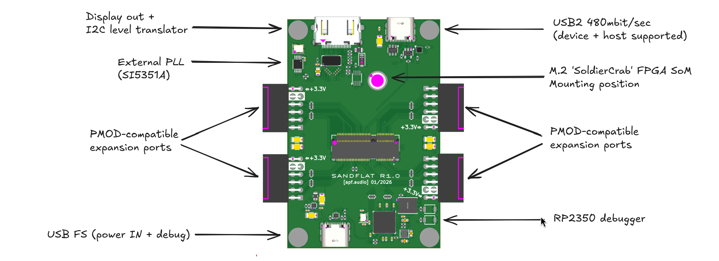
This repository contains a few example projects which run on SandFlat:
src/top/blink.py: Simplest example blinking the SoldierCrab LEDssrc/top/dsp.py: DSP examples based on Tiliqua's DSP library, streaming all audio in/out the USB2 port.src/top/colorbar.py: Video example showing color bars at 640x480p60src/top/vectorscope.py: Vectorscope example taking audio from a USB stream and rendering it to a framebuffer in PSRAM out over video.A freshly manufactured SandFlat first needs pico-dirtyJtag flashed to the RP2350. - A working version is available on this branch of my pico-dirtyJtag fork.
Once your RP2350 is bootstrapped, you should be able to see the ECP5 with openFPGALoader:
$ openFPGALoader -c dirtyJtag --detectNow, you can build one of the examples. After installing PDM, install all the dependencies and build a bitstream:
pdm install
pdm dsp build --core=mirror
This will synthesize a build/top.bit which enumerates as a USB2 audio device which sends all input audio (computer loudspeaker out) back out to the outputs (computer mic in). To flash it to the FPGA:
$ openFPGALoader -c dirtyJtag build/top.bitNote: this will not persist unless you write it to flash permanently with -f.
Design files for R1.0 of the hardware are in hardware/. This version has been brought up and is largely working, with a couple of minor bugs found:
hardware/folder.SandFlat is not generally available yet, however if you are interested in trying it out, feel free to email me, I may have a few prototypes to spare.
For updates, join the matrix chatroom, or my own mailing list.
Participants in this project are expected to adhere to the Berlin Code of Conduct.
We would like to acknowledge partial funding of the Tiliqua project from the NGI Commons Fund, a fund established by NLnet with financial support from the European Commission’s Next Generation Internet program.

The hardware and gateware in this project is largely covered under the CERN Open-Hardware License V2 CERN-OHL-S, mirrored in the LICENSE text in this repository. Some gateware and software is covered under the BSD 3-clause license - check the header of the individual source files for specifics.
| Qty | Value | Footprint | References |
|---|---|---|---|
| 10 | 0.1uF | Capacitor_SMD:C_0402_1005Metric | C3, C4, C5, C6, C7, C8, C12, C13, C14, C36 |
| 10 | 33R | Resistor_SMD:R_Array_Convex_4x0402 | RN1, RN2, RN3, RN4, RN5, RN6, RN7, RN8, RN9, RN10 |
| 8 | 100nF | Capacitor_SMD:C_0201_0603Metric | C46, C47, C48, C49, C50, C51, C52, C53 |
| 8 | 4K7 | Resistor_SMD:R_0402_1005Metric | R1, R2, R9, R19, R25, R26, R44, R50 |
| 7 | 22uF | Capacitor_SMD:C_1206_3216Metric | C15, C16, C22, C24, C26, C29, C32 |
| 4 | 100nF | Capacitor_SMD:C_0402_1005Metric | C27, C28, C35, C37 |
| 4 | 33R | Resistor_SMD:R_0402_1005Metric | R40, R41, R47, R48 |
| 4 | Conn_02x06_Top_Bottom | Connector_PinSocket_2.54mm:PinSocket_2x06_P2.54mm_Horizontal | J1, J2, J3, J4 |
| 4 | MountingHole_Pad | MountingHole:MountingHole_3.2mm_M3_Pad_Via | H1, H2, H4, H5 |
| 3 | 10K | Resistor_SMD:R_0402_1005Metric | R23, R27, R33 |
| 3 | 27R | Resistor_SMD:R_0402_1005Metric | R4, R5, R6 |
| 3 | 4.7uF | Capacitor_SMD:C_0603_1608Metric | C9, C10, C11 |
| 3 | 47K | Resistor_SMD:R_0402_1005Metric | R36, R37, R42 |
| 2 | 100K | Resistor_SMD:R_0402_1005Metric | R3, R7 |
| 2 | 12pF | Capacitor_SMD:C_0402_1005Metric | C1, C2 |
| 2 | 2K2 | Resistor_SMD:R_0402_1005Metric | R28, R31 |
| 2 | 4.7uF | Capacitor_SMD:C_0805_2012Metric | C44, C45 |
| 2 | 5.1K | Resistor_SMD:R_0402_1005Metric | R11, R12 |
| 2 | LOGO | LOGO | G***, G*** |
| 2 | USB_C_Receptacle_USB2.0_14P | Connector_USB:USB_C_Receptacle_GCT_USB4105-xx-A_16P_TopMnt_Horizontal | J5, J7 |
| 1 | 15V 50mA | Fuse:Fuse_0805_2012Metric | F3 |
| 1 | 18K | Resistor_SMD:R_0402_1005Metric | R24 |
| 1 | 2.2uH | Inductor_SMD:L_0805_2012Metric | L8 |
| 1 | 200K | Resistor_SMD:R_0402_1005Metric | R38 |
| 1 | 210K | Resistor_SMD:R_0402_1005Metric | R39 |
| 1 | 25MHz AMB8G | Crystal:Crystal_SMD_3225-4Pin_3.2x2.5mm | Y2 |
| 1 | 2K | Resistor_SMD:R_0402_1005Metric | R8 |
| 1 | 3.3uH | Inductor_SMD:L_Wuerth_MAPI-2512 | L1 |
| 1 | 6.8pF | Capacitor_SMD:C_0402_1005Metric | C17 |
| 1 | 900K (910K) | Resistor_SMD:R_0402_1005Metric | R20 |
| 1 | AP2161W | Package_TO_SOT_SMD:SOT-23-5 | U9 |
| 1 | B0520LW | Diode_SMD:D_SOD-123 | D4 |
| 1 | CM4012M00012001 | Crystal:Crystal_SMD_2520-4Pin_2.5x2.0mm | Y1 |
| 1 | DVI_GPDI | Connector_Video:HDMI_A_Amphenol_10029449-x01xLF_Horizontal | J10 |
| 1 | MICROMOD-2222 | m2:TE_21992304 | J8 |
| 1 | MountingHole | m2:mounting_hole | H3 |
| 1 | PCA9306 | Package_SO:SSOP-8_2.95x2.8mm_P0.65mm | U14 |
| 1 | PI3HDX511E | Package_DFN_QFN:Diodes_ZL32_TQFN-32-1EP_3x6mm_P0.4mm_EP1.25x3.5mm | U13 |
| 1 | RP2350-A | Package_DFN_QFN_Extra:QFN-60_EP_7x7_Pitch0.4mm | U4 |
| 1 | SW_BOOTSEL | Button_Switch_SMD:SW_SPST_B3U-1000P | SW2 |
| 1 | SW_RESET | Button_Switch_SMD:SW_SPST_B3U-1000P | SW1 |
| 1 | Si5351A-B-GT | Package_SO:MSOP-10_3x3mm_P0.5mm | U11 |
| 1 | TLV62569ADRLR | Package_TO_SOT_SMD:SOT-563 | U10 |
| 1 | TUSB322I | Package_DFN_QFN:Texas_X2QFN-12_1.6x1.6mm_P0.4mm | U8 |
| 1 | USBLC6-2P6 | Package_TO_SOT_SMD:SOT-666 | U1 |
| 1 | USBLC6-4SC6 | Package_TO_SOT_SMD:SOT-23-6 | U3 |
| 1 | W25Q128JVPIQ | Package_SON:WSON-8-1EP_6x5mm_P1.27mm_EP3.4x4mm | U2 |
The 112 most common of 113 parts.
It measures 50 × 75 mm and has 6 copper layers, 1.19 mm thick.
113 parts, built around the W25Q128JVPIQ, AP2161WG, PCA9306D and SI5351A-B-GT. The full list of its parts is on this page, with links to each part's symbol and footprint where PCBKit's library has them.
From the apfaudio/sandflat repository on GitHub, at the commit this page was made from: the board is hardware/sandflat/sandflat.kicad_pcb and its schematic hardware/sandflat/gpdi.kicad_sch. PCBKit opens the board in the browser, with nothing to install.
Its repository publishes it under the CERN-OHL-S-2.0 licence: you may reuse it on that licence's terms (keep the author's notice, and for a copyleft licence share your changes alike).

AcheronProject/Doddle60
Doddle60 is a 60% ISO layout PCB with a minimal layout number support intended for ISO users.


moonbuggy/GPIO-power-switch
A low-side MOSFET switch controlled by a button and GPIO signals

Tinkerforge/distance-us-v2-bricklet-techniker
This repository contains the firmware source code and the hardware design files. The documentation generator configs can be found at https://github.com/Tinkerforge/generators


