2 layers160 × 95 mm
Placa Control Fuentes y Carga
edgranzella/Placa-de-Corte-TX
Circuito Impreso de la plaquetita de Corte TX que va apilada sobre el Arduino Nano de la placa Controladora de Fuentes y Carga.
142 parts

 antoinem01/torqeedo_motor
Arduino sketch to control a Torqeedo electric outboard motor over RS485, with speed control and safety switches
Torqeedo pcb is an open-source printed circuit board by antoinem01, from the antoinem01/torqeedo_motor repository on GitHub, published under the GPL-3.0 licence. It is a 2-layer board of 100 × 80 mm with 43 parts on 26 nets, routed with 203 tracks and 32 vias.
It is built around the ATMEGA328P-PU, MAX485ED and SM712, with the SS34 among its other parts. Its parts include 13 capacitors, 8 resistors, 2 ICs, 1 diode and 1 switch. It belongs with the interfaces and adapters and robots and motor control boards and the AVR (ATmega, ATtiny) boards of this library.


Schema en printontwerp voor de geïntegreerde besturingsprint uit
../../docs/pcb-geintegreerd.md.
| Bestand | Inhoud |
|---|---|
torqeedo_pcb.kicad_pro | projectbestand — open dit in KiCad |
torqeedo_pcb.kicad_sch | schema (netlist, footprints toegewezen) |
torqeedo_pcb.kicad_pcb | printontwerp: geplaatst, gerouteerd, massavlakken |
fab/ | Gerbers + boorbestanden (*-gerbers.zip), BOM, plaatsingsbestand |
pcb-top.png / pcb-bottom.png | 3D-weergave van boven- en onderkant |
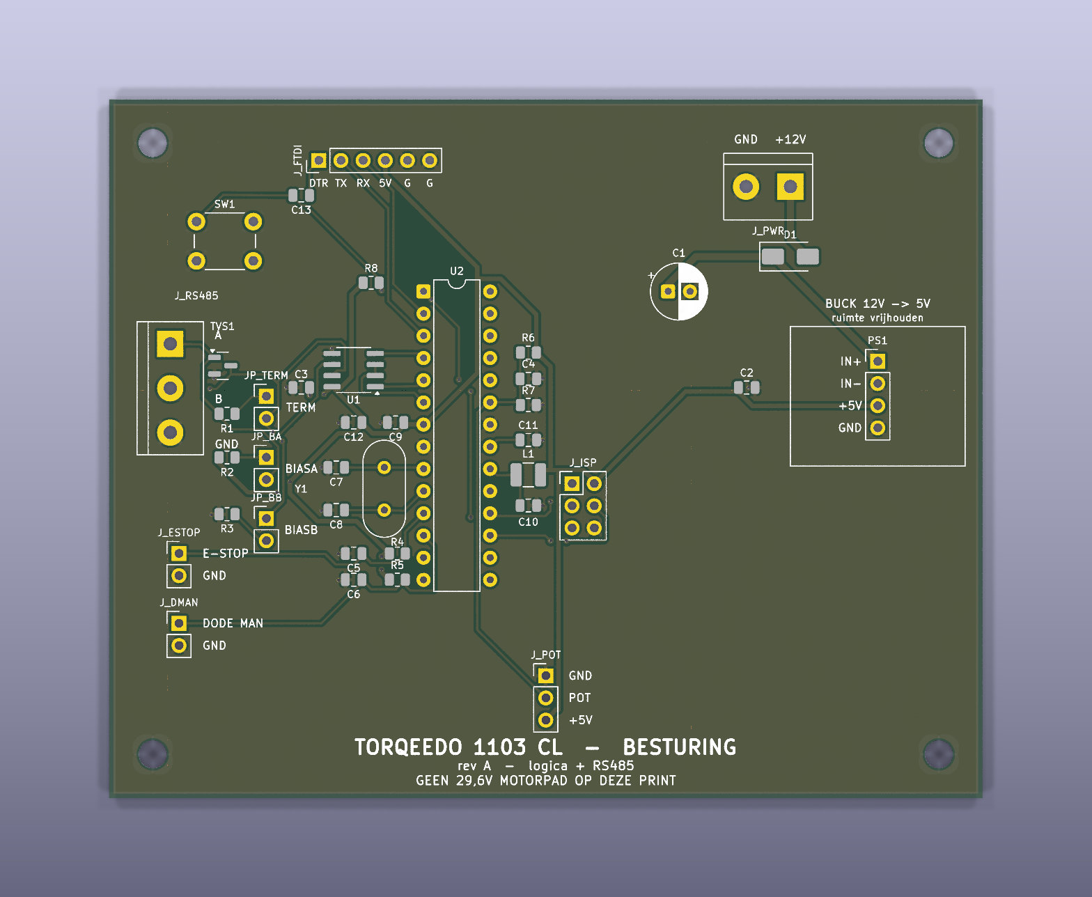
De symbolen zijn in het schema ingebed; de footprints komen uit de standaard KiCad-bibliotheken (KiCad 9). Geen externe libraries nodig.
| Formaat | 100 × 80 mm, 2 lagen, 1,6 mm |
| Montage | 4× M3 (⌀3,2 mm) op 5 mm van elke hoek |
| Koperlagen | F.Cu = signalen, B.Cu = doorlopend massavlak (92,8 % dicht, één eiland) |
| Baanbreedtes | 0,25 mm signaal · 0,50 mm +5 V/GND · 0,80 mm +12 V |
| Via's | 0,7 mm pad / 0,35 mm boring — 32 stuks, waarvan 15 stitching-via's naar het massavlak |
| Clearance | 0,25 mm (netclasses Default / Power / HV staan in het projectbestand) |
De onderlaag is bewust bijna onaangeroerd gelaten: alleen een handvol korte oversteekjes, zodat het massavlak een aaneengesloten retourpad blijft.
 ┌──────────────────────────────────────────────────────────┐
 │  SW1  C13   J_FTDI                          J_PWR  D1    │  ← 12 V in, ompoling
 │                                        C1        ┌─────┐ │
 │ J_RS485  TVS1  JP_*   U1      U2    R6/C4/R7  C2 │BUCK │ │  ← 12 V→5 V module
 │   A/B/G  R1-R3        MAX485  ATmega  C11        │PS1  │ │     (ruimte vrij)
 │                       C3      328P    L1/C10     └─────┘ │
 │                   C7 Y1 C8            J_ISP              │
 │ J_ESTOP    C5/C6  R4/R5                                  │
 │ J_DMAN                     J_POT                         │
 │            TORQEEDO 1103 CL - BESTURING  rev A           │
 └──────────────────────────────────────────────────────────┘
De plaatsing volgt de aandachtspunten uit
pcb-geintegreerd.md §11:
Op de silkscreen staan de aansluitingen benoemd (+12V/GND, A/B/GND,
POT, E-STOP, DODE MAN, IN+/IN-/+5V/GND, DTR TX RX 5V G G), plus
het gereserveerde vlak voor de buck-module.
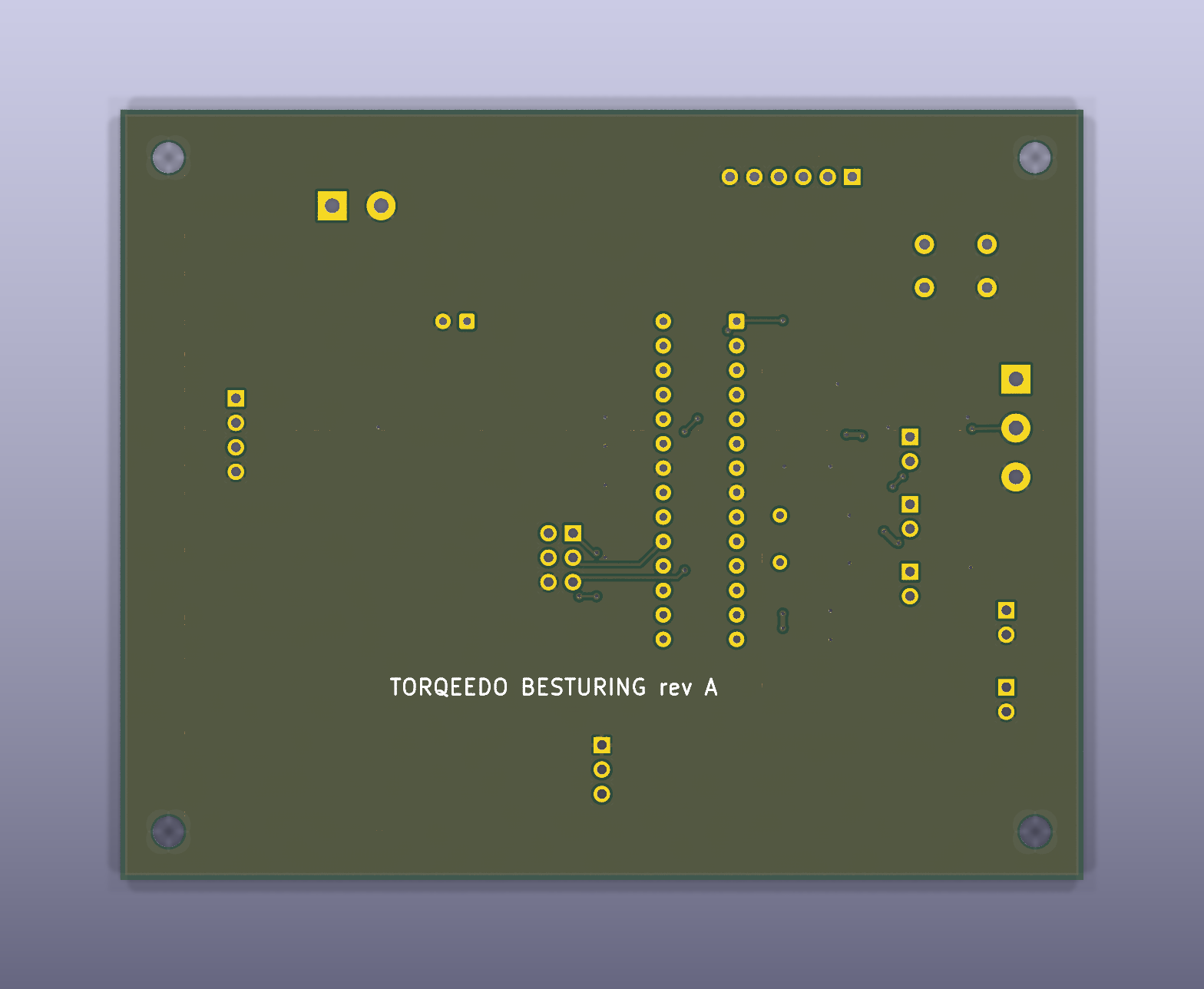
Gecontroleerd met KiCad 9.0.2:
Dit is een ontwerp-verificatie, geen gebouwde print. Zie hieronder wat je vóór bestellen zelf moet nakijken.
+12V_PROT-kant; zo is hij bedraad,
controleer de silk-oriëntatie.CP_Radial toe en let op polariteit.pcb-geintegreerd.md §5).kicad-cli pcb export gerbers --no-protel-ext \
--layers F.Cu,B.Cu,F.Mask,B.Mask,F.Silkscreen,B.Silkscreen,F.Paste,Edge.Cuts \
-o fab/ torqeedo_pcb.kicad_pcb
kicad-cli pcb export drill --format excellon --excellon-separate-th -o fab/ torqeedo_pcb.kicad_pcb
kicad-cli pcb export pos --format csv --units mm --side both -o fab/torqeedo_pcb-pos.csv torqeedo_pcb.kicad_pcb
kicad-cli pcb drc --severity-error --severity-warning torqeedo_pcb.kicad_pcbfab/torqeedo_pcb-gerbers.zip is wat je bij een fabrikant (JLCPCB, Aisler,
Eurocircuits) uploadt. Standaard 2-laags 1,6 mm proces; de kleinste maten op de
print (0,25 mm baan, 0,35 mm boring) zitten ruim binnen wat iedereen aankan.
De referenties J_PWR, J_POT, JP_BA, … eindigen niet op een cijfer. KiCad
ziet zulke namen als niet-geannoteerd en meldt dat bij het openen van het
schema; in de BOM verschijnen ze als J_PWR?. Dat is cosmetisch — netlist,
print en fabricagebestanden zijn correct (de print gebruikt de namen zonder
?). Wil je het weg hebben, hernoem dan in het schema naar bijvoorbeeld
J_PWR1; dan moeten de verwijzingen in docs/pcb-geintegreerd.md mee.
| Qty | Value | Footprint | References |
|---|---|---|---|
| 8 | 100nF | Capacitor_SMD:C_0805_2012Metric | C3, C4, C5, C6, C9, C10, C11, C13 |
| 4 | H1, H2, H3, H4 | ||
| 3 | 10k | Resistor_SMD:R_0805_2012Metric | R4, R5, R8 |
| 2 | 100k | Resistor_SMD:R_0805_2012Metric | R6, R7 |
| 2 | 10uF | Capacitor_SMD:C_0805_2012Metric | C2, C12 |
| 2 | 22pF | Capacitor_SMD:C_0805_2012Metric | C7, C8 |
| 2 | 560 | Resistor_SMD:R_0805_2012Metric | R2, R3 |
| 1 | +12V in | TerminalBlock:TerminalBlock_bornier-2_P5.08mm | J_PWR |
| 1 | 100uF/25V | Capacitor_THT:CP_Radial_D6.3mm_P2.50mm | C1 |
| 1 | 10uH | Inductor_SMD:L_1210_3225Metric | L1 |
| 1 | 120 | Resistor_SMD:R_0805_2012Metric | R1 |
| 1 | 120R term | Connector_PinHeader_2.54mm:PinHeader_1x02_P2.54mm_Vertical | JP_TERM |
| 1 | 16MHz | Crystal:Crystal_HC49-U_Vertical | Y1 |
| 1 | ATmega328P-PU | Package_DIP:DIP-28_W7.62mm | U2 |
| 1 | Buck 12V->5V | Connector_PinHeader_2.54mm:PinHeader_1x04_P2.54mm_Vertical | PS1 |
| 1 | Dode man NO | Connector_PinHeader_2.54mm:PinHeader_1x02_P2.54mm_Vertical | J_DMAN |
| 1 | FTDI | Connector_PinHeader_2.54mm:PinHeader_1x06_P2.54mm_Vertical | J_FTDI |
| 1 | ISP | Connector_PinHeader_2.54mm:PinHeader_2x03_P2.54mm_Vertical | J_ISP |
| 1 | MAX485 | Package_SO:SOIC-8_3.9x4.9mm_P1.27mm | U1 |
| 1 | Noodstop NC | Connector_PinHeader_2.54mm:PinHeader_1x02_P2.54mm_Vertical | J_ESTOP |
| 1 | Potmeter | Connector_PinHeader_2.54mm:PinHeader_1x03_P2.54mm_Vertical | J_POT |
| 1 | RS485 bus | TerminalBlock:TerminalBlock_bornier-3_P5.08mm | J_RS485 |
| 1 | Reset | Button_Switch_THT:SW_PUSH_6mm | SW1 |
| 1 | SM712 | Package_TO_SOT_SMD:SOT-23 | TVS1 |
| 1 | SS34 | Diode_SMD:D_SMA | D1 |
| 1 | bias A | Connector_PinHeader_2.54mm:PinHeader_1x02_P2.54mm_Vertical | JP_BA |
| 1 | bias B | Connector_PinHeader_2.54mm:PinHeader_1x02_P2.54mm_Vertical | JP_BB |
edgranzella/Placa-de-Corte-TX
Circuito Impreso de la plaquetita de Corte TX que va apilada sobre el Arduino Nano de la placa Controladora de Fuentes y Carga.


EdgeCoil/wiegand-bridge
ESP32-S3 Wiegand reader bridge for Home Assistant: 4-layer board, BOM and ESPHome firmware.

NGOQUOC98/ESP32_MODBUS_PCB_MASTER
This project was in development phase - we will remove this remark after release

ibScale/ibScaleFeederLite
ibScale Lite Feeder for the LumenPNP


It measures 100 × 80 mm and has 2 copper layers, 1.6 mm thick.
43 parts, built around the ATMEGA328P-PU, MAX485ED, SM712 and SS34. The full list of its parts is on this page, with links to each part's symbol and footprint where PCBKit's library has them.
From the antoinem01/torqeedo_motor repository on GitHub, at the commit this page was made from: the board is hardware/kicad/torqeedo_pcb.kicad_pcb and its schematic hardware/kicad/torqeedo_pcb.kicad_sch. PCBKit opens the board in the browser, with nothing to install.
Its repository publishes it under the GPL-3.0 licence: you may reuse it on that licence's terms (keep the author's notice, and for a copyleft licence share your changes alike).