6 layers100 × 70 mm
Sa800u baseboard hw
antmicro/snapdragon-845-baseboard
https://antmicro.com/blog/2022/04/open-source-snapdragon-845-baseboard/
616 parts70Apache-2.0
 antmicro/flickerless-led-driver2
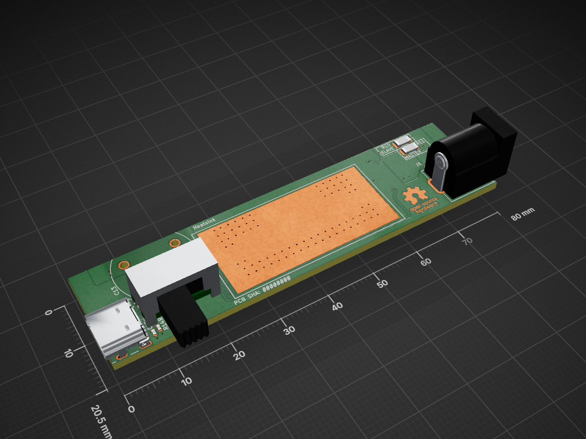
This project contains open hardware design files for a PCB supporting a pair of infrared (IR) LEDs in an LZ1 LuxiGen package from OSRAM.
Lz1-led driver is an open-source printed circuit board by antmicro, from the antmicro/flickerless-led-driver repository on GitHub, published under the Apache-2.0 licence. It is a 2-layer board of 80 × 20.5 mm with 44 parts on 27 nets, routed with 161 tracks and 101 vias.
It is built around the MP2483DQ-LF-P, MCMR12X000 PTL and SM02B-SRSS-TB(LF)(SN), with the LZ1-00R802-0000, CR0402-FX-1002GLF and CR0402-FX-2202GLF among its other parts. Its parts include 16 resistors, 13 capacitors, 4 connectors, 3 diodes and 2 ICs.


Copyright (c) 2023-2024 Antmicro
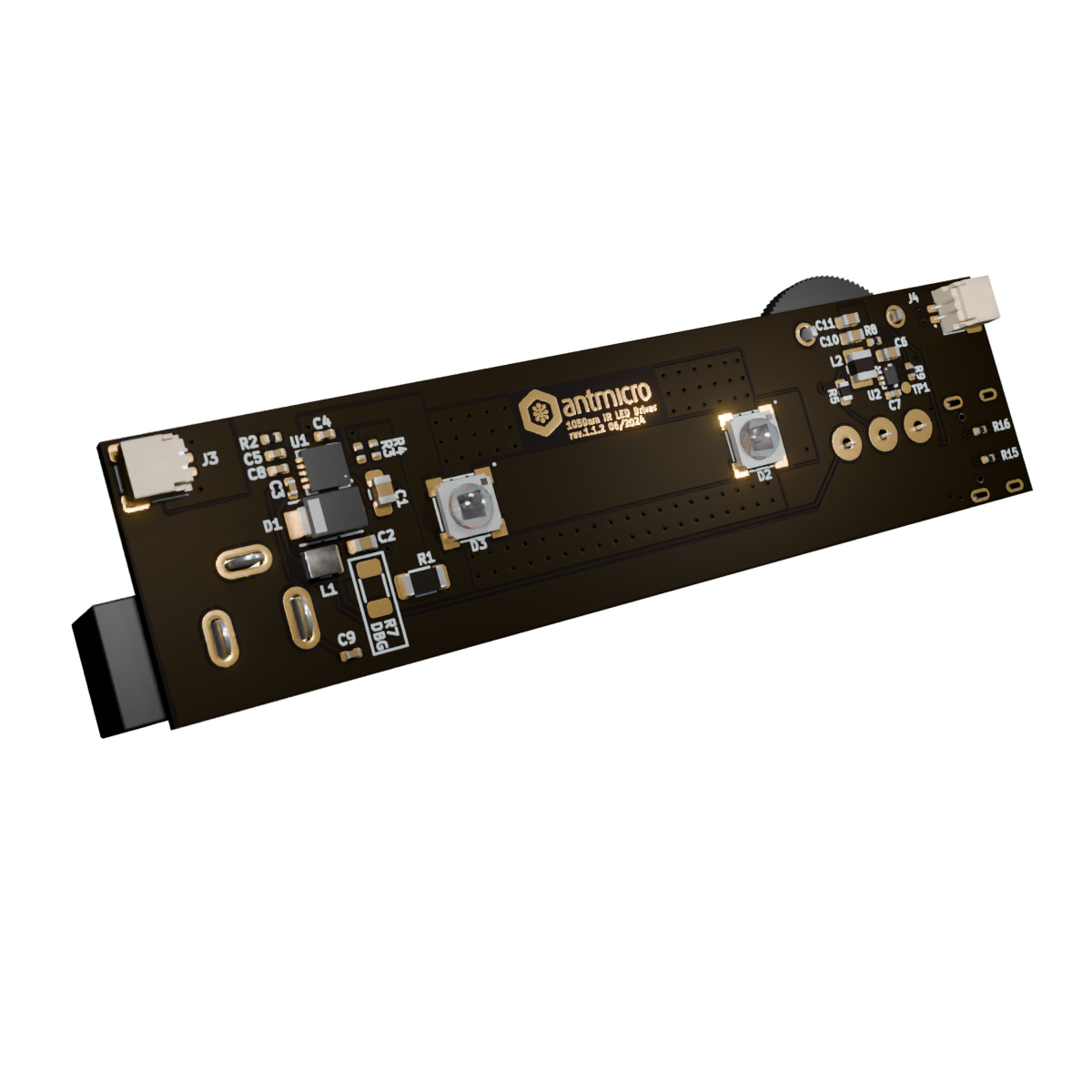
This project contains open hardware design files for a PCB supporting a pair of infrared (IR) LEDs in an LZ1 LuxiGen package from OSRAM. The PCB includes a flickerless LED driver that allows adjusting LED brightness with a potentiometer. This design can be easily adopted to other LEDs and eventually can become a custom LED driver providing precise lighting for machine vision applications. You can read more about flickerless LED driving in a dedicated blog note. The design files were prepared in KiCad 7.x.
The main directory contains KiCad PCB project files, a LICENSE, and a README. The remaining files are stored in the following directories:
img - contains graphics for this READMEdoc - contains schematics in pdf formassets - contains visual assets for showcasing this design on Open Hardware Portal.The project contains one PCB that can be configured as a primary or a secondary board, depending on the assembly variant. It is designed to be powered with 12V DC using a barrel jack.
This version contains the LED driver, all the connectors and a potentiometer.
There are 3 connectors located on the primary board:
A rotary potentiometer is the element that provides control of diode brightness using the LED driver.
This variant contains only the LZ1 diodes, 2-pin connectors and resistors marked as secondary DP (R10 and R7).
It is powered and controlled by the primary board through JST connectors.
To configure the primary board as a standalone, mount the R7 Debug jumper in addition to R11.
To daisy chain the boards, R7 CANNOT be populated on the primary board and must be populated on secondary boards.
C_out of one board must be connected to A_in of another one.
The design was made for up to 3 boards in a chain.
This project is published under the Apache-2.0 license.
| Qty | Value | Footprint | References |
|---|---|---|---|
| 6 | C_100n_0402 | antmicro-footprints:C_0402_1005Metric | C3, C7, C8, C9, C12, C13 |
| 3 | R_0R_1206 | antmicro-footprints:R_1206_3216Metric | R7, R10, R11 |
| 2 | C_1n0_0402 | antmicro-footprints:C_0402_1005Metric | C4, C5 |
| 2 | C_22u_0603 | antmicro-footprints:C_0603_1608Metric | C10, C11 |
| 2 | JST_SH_1x2_SM02B-SRSS-TB-LF-SN | antmicro-footprints:Conn_JST_SH_1x2_SM02B-SRSS-TB-LF-SN | J3, J4 |
| 2 | LED_IR_LZ1-00R802 | antmicro-footprints:LED_IR_LZ1-00R802 | D2, D3 |
| 2 | R_10k_0402 | antmicro-footprints:R_0402_1005Metric | R12, R14 |
| 2 | R_22k_0402 | antmicro-footprints:R_0402_1005Metric | R15, R16 |
| 1 | AP62301Z6-7 | antmicro-footprints:SOT-563 | U2 |
| 1 | B360A-M3 | antmicro-footprints:D_SMA | D1 |
| 1 | BarrelJack_Pin2mm_MJ-179PH | antmicro-footprints:BarrelJack_Pin2mm_MJ-179PH | J1 |
| 1 | C_10u_0805 | antmicro-footprints:C_0805_2012Metric | C1 |
| 1 | C_10u_25V_0603 | antmicro-footprints:C_0603_1608Metric | C6 |
| 1 | C_2u2_0603 | antmicro-footprints:C_0603_1608Metric | C2 |
| 1 | L_3u3_2.5A_1008 | antmicro-footprints:L_1008_2520Metric | L2 |
| 1 | L_4u7_1.55A_Bourns-SRP2512A | antmicro-footprints:L_Bourns-SRP2512A | L1 |
| 1 | MP2483DQ-LF-P | antmicro-footprints:QFN-10-1EP_3x3mm_P0.5mm | U1 |
| 1 | POT_20k_R0141-2-20k | antmicro-footprints:POT_R0141-2 | POT1 |
| 1 | R_0R2_1206 | antmicro-footprints:R_1206_3216Metric | R1 |
| 1 | R_100R_0402 | antmicro-footprints:R_0402_1005Metric | R13 |
| 1 | R_18k_0402 | antmicro-footprints:R_0402_1005Metric | R3 |
| 1 | R_1k3_0402 | antmicro-footprints:R_0402_1005Metric | R9 |
| 1 | R_20k_0402 | antmicro-footprints:R_0402_1005Metric | R6 |
| 1 | R_2k_0402 | antmicro-footprints:R_0402_1005Metric | R4 |
| 1 | R_300k_0603 | antmicro-footprints:R_0603_1608Metric | R5 |
| 1 | R_39k_0402 | antmicro-footprints:R_0402_1005Metric | R2 |
| 1 | R_6k8_0402 | antmicro-footprints:R_0402_1005Metric | R8 |
| 1 | TP_1mm_SMD | antmicro-footprints:TP_SMD_1mm | TP1 |
| 1 | USB-C_GCT_USB4105-GF-A | antmicro-footprints:USB-C_Receptacle_GCT_USB4105-GF-A | J2 |
| 1 | antmicro_logo | antmicro-footprints:antmicro-logo_scaled_12mm | N1 |
| 1 | oshw_logo | antmicro-footprints:oshw-logo | N2 |
It measures 80 × 20.5 mm and has 2 copper layers, 1.6 mm thick.
44 parts, built around the MP2483DQ-LF-P, MCMR12X000 PTL, SM02B-SRSS-TB(LF)(SN) and LZ1-00R802-0000. The full list of its parts is on this page, with links to each part's symbol and footprint where PCBKit's library has them.
From the antmicro/flickerless-led-driver repository on GitHub, at the commit this page was made from: the board is lz1-led-driver.kicad_pcb and its schematic led_connector.kicad_sch. PCBKit opens the board in the browser, with nothing to install.
Its repository publishes it under the Apache-2.0 licence: you may reuse it on that licence's terms (keep the author's notice, and for a copyleft licence share your changes alike).
antmicro/snapdragon-845-baseboard
https://antmicro.com/blog/2022/04/open-source-snapdragon-845-baseboard/

tscircuit/dataset-srj24
Ten production-oriented KiCad boards converted to Simple Route JSON

antmicro/scalenode-cm4-baseboard
Baseboard for Raspberry Pi 4 Compute Module optimized for clustering

antmicro/d1600e-psu-breakout
Breakout board for DELL D1600E-S0 Power Supply Unit

antmicro/ecp5-dc-scm
Experimental Lattice ECP5-driven Data Center Security Communication Module

antmicro/jetson-nano-baseboard
Antmicro's open hardware baseboard for the NVIDIA Jetson Nano, TX2 NX and Xavier NX

CopperPilot/Jetson-AI-Cam-CopperPilot
A carrier for Jetson Nano, Xavier NX and TX2 NX with two IMX219 cameras on a 39 mm stereo baseline, dual 4K outputs and CAN.
