2 layers

 anthonydotmoe/vgmplayer4
(Unfinished) Hardware YM2151 VGM Player using RP2040
Module board is an open-source printed circuit board by anthonydotmoe, from the anthonydotmoe/vgmplayer repository on GitHub. It is a 2-layer board of 111.8 × 88.9 mm with 28 parts on 77 nets, routed with 296 tracks and 48 vias.
It is built around the NJM4556AM. Its parts include 10 connectors, 8 capacitors, 7 ICs and 2 resistors. It belongs with the RP2040 boards of this library.
"It's a work in progress"
2018 This project started out using an ATMEGA328P and Arduino, but I found that it was hard to write fast enough code to play songs at full speed. I then found the STM32 series of microcontrollers; It was promising, but I really didn't like the SDK or the HAL that was provided for these parts. After a few years, the Raspberry Pi Foundation released the Raspberry Pi Pico. I bought the board during its pre-order stage simply because it's a $5 microcontroller. This new board, with their own RP2040 chip, has one key feature that I didn't know at the time will make this project viable for me. The Programmable I/O (PIO).
2022 I finally got to looking at the datasheet for this board during DEFCON 2022, where they used the RP2040 for their interactive badge. The PIO section caught my eye, but I didn't look into it until a month later.
When I read the examples they had for driving WS2812 LED strips, I realized what I could do with this extra power. I could easily get data to the chip on time, every time; and have plenty of time for drawing a UI to a screen, fetching data from an SD card over SPI, and in the future, emulating other sound chips for game systems with AD/PCM and other chips.
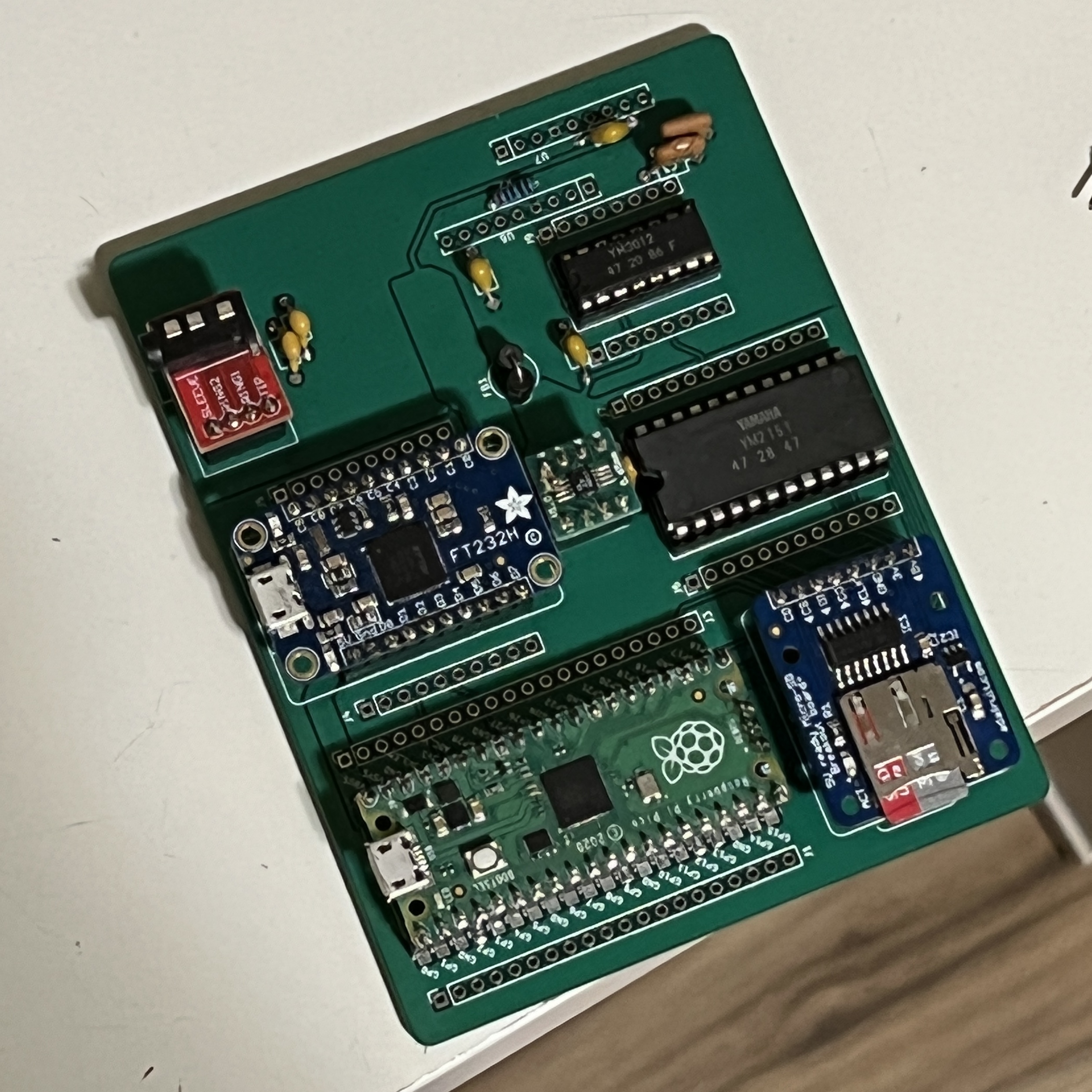
I made this development board for the project.
GPIO 0-7 are connected to D0-D7 on the YM2151. GPIO 8-10 are connected to the
A0, WR, and CS pins. I'm using SPI to connect to the SD card, and an
LTC6903 programmable clock generator making the main clock for the YM2151.
The supporting circuitry for the YM2151 was ripped from the same place I got the chip from, a Yamaha CX5 Music Computer.
To be documented... and written
Special thanks to:
.vgm files is really helpful for me.| Qty | Value | Footprint | References |
|---|---|---|---|
| 4 | 100nF | Capacitor_THT:C_Axial_L3.8mm_D2.6mm_P7.50mm_Horizontal | C1, C2, C7, C8 |
| 2 | 3300pF | Capacitor_THT:C_Axial_L3.8mm_D2.6mm_P7.50mm_Horizontal | C3, C4 |
| 2 | C | Capacitor_THT:C_Axial_L3.8mm_D2.6mm_P7.50mm_Horizontal | C5, C6 |
| 2 | Conn_01x08_Female | Connector_PinHeader_2.54mm:PinHeader_1x08_P2.54mm_Vertical | J8, J9 |
| 2 | Conn_01x10_Female | Connector_PinSocket_2.54mm:PinSocket_1x10_P2.54mm_Vertical | J4, J5 |
| 2 | Conn_01x12_Female | Connector_PinHeader_2.54mm:PinHeader_1x12_P2.54mm_Vertical | J6, J7 |
| 2 | Conn_01x20_Female | Connector_PinSocket_2.54mm:PinSocket_1x20_P2.54mm_Vertical | J1, J3 |
| 2 | NJM4556A | Package_SIP:SIP-9_22.3x3mm_P2.54mm | U6, U7 |
| 1 | 100 | Resistor_THT:R_Axial_DIN0204_L3.6mm_D1.6mm_P5.08mm_Horizontal | R2 |
| 1 | 1k | Resistor_THT:R_Axial_DIN0204_L3.6mm_D1.6mm_P5.08mm_Horizontal | R1 |
| 1 | 220Ω at 100MHz | Ferrite_THT:LairdTech_28C0236-0JW-10 | FB1 |
| 1 | AudioJack4 | YM Libraries:AudioJack4 | J10 |
| 1 | FT232H_Breakout | YM Libraries:Adafruit_FT232H_Breakout | U3 |
| 1 | LTC6903 | Package_DIP:DIP-8_W7.62mm_Socket | U2 |
| 1 | Micro_SD_Card_Breakout | YM Libraries:Adafruit_Micro-SD_Card_Breakout | J2 |
| 1 | Pico | MCU_RaspberryPi_and_Boards:RPi_Pico_SMD_TH | U1 |
| 1 | YM2151 | Package_DIP:DIP-24_W15.24mm_Socket | U4 |
| 1 | YM3012 | Package_DIP:DIP-16_W7.62mm_Socket | U5 |

hiro-akihabara/OpnBeat
OpnBeat is open source Lo-fi sampler project

electrified/rc2014-ym2151
Yamaha's DX21, DX27 and DX100 synthesisers used a derivative IC which is very similar.

bradport02/RX8-Infotainment_System
An infotainment system for the Mazda RX-8 that integrates seamlessly with the climate control unit.


SmittyHalibut/station-console
A station console, to connect an operator, logger, and radio together.


facarvalho/MeetingHub-4
Analog audio hub for 4 laptops — monitor all four at once (per-source + master volume), speak on one at a time with a physical mic selector, use one ordinary TRRS headset, install nothing on any laptop.
It measures 111.8 × 88.9 mm and has 2 copper layers, 1.6 mm thick.
28 parts, built around the NJM4556AM. The full list of its parts is on this page, with links to each part's symbol and footprint where PCBKit's library has them.
From the anthonydotmoe/vgmplayer repository on GitHub, at the commit this page was made from: the board is hardware/module_board/module_board.kicad_pcb and its schematic hardware/gb_board/gb_board.kicad_sch. PCBKit opens the board in the browser, with nothing to install.
Its repository states no licence, so its author keeps all rights: ask anthonydotmoe before reusing the design.