2 layers37.3 × 14.7 mm
Pi2co usb
ansemjo/pi2co-usb
USB to I2C bridge using an Atmel AVR ATtiny85V and even more tiny than I2C-Tiny-USB.
31 parts4GPL-2.0

 ansemjo/pi2co-usb4
USB to I2C bridge using an Atmel AVR ATtiny85V and even more tiny than I2C-Tiny-USB.
Panel is an open-source printed circuit board by ansemjo, from the ansemjo/pi2co-usb repository on GitHub, published under the GPL-2.0 licence. It is a 2-layer board of 95.6 × 95.5 mm with 492 parts on 170 nets, routed with 1,680 tracks and 330 vias.
It is built around the ATTINY85-20PU, ATTINY85-20SU and MIC5504-3.3YM5, with the BSD840NH6327XTSA1 among its other parts. Its parts include 80 resistors, 40 connectors, 30 capacitors, 30 ICs and 30 diodes. It belongs with the interfaces and adapters boards and the AVR (ATmega, ATtiny) boards of this library.


This project is based on i2c-tiny-usb by Till Harbaum and the V-USB stack by Objective Development. It uses the fact that you can implement a low-speed USB device with the IO pins on an Atmel AVR chip to create a very simple I2C bridge.
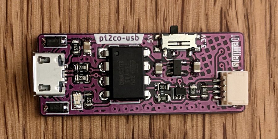
In the original i2c-tiny-usb implementation, an Atmel AVR ATtiny45 was used with an external oscillator. Unfortunately this also meant that you needed to use all six pins on the chip – including the RESET pin. Should anything ever go wrong you would need a high-voltage serial programmer (HVSP).
On more recent Digispark devices, which use an ATtiny85, a modified version of the V-USB stack is used. They use only the internal PLL oscillator calibrated to 16.5 MHz. No external crystal is required, ISP remains available and you can even connect an indicator LED on the remaining pin!
In 2020 I soldered a protype with a DIP ATtiny85 and a small leftover piece of protoboard – enough to build myself an I2C bridge! This year I updated the design and created a custom PCB in KiCad. It brings an additional voltage regulator for 3.3V, a selection slider between the two available voltages, a bidirectional level shifter based on two N-channel MOSFETs and a standard JST-SH connector; the latter is used by a number of different maker vendors under the names Qwiic (SparkFun) or STEMMA QT (Adafruit). Note: for interoperability with Qwiic devices always use 3.3V!
The schematic and the KiCad project can be found in hardware/.
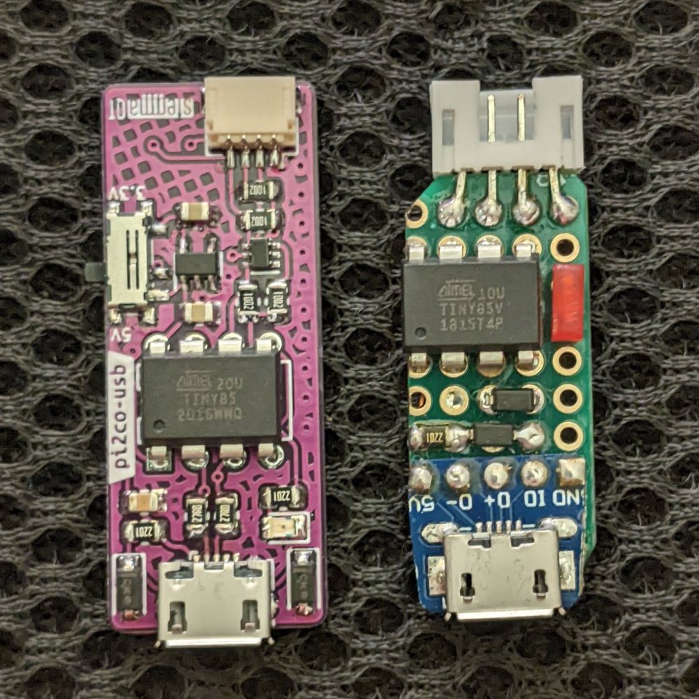
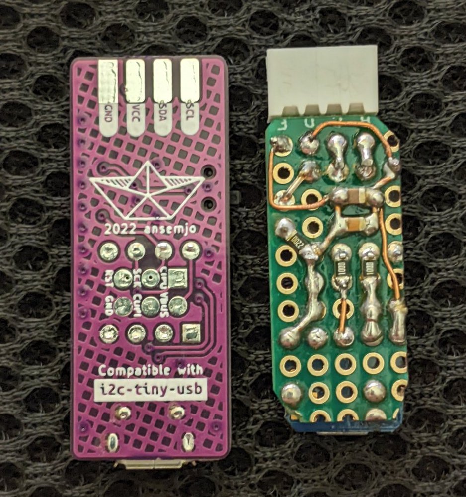
Since the ATtiny85 is basically the same, you can use the exact same bootloader and firmware as I used for the prototype; the rest of this README thus still applies.
The firmware is almost fully plucked from Till Harbaum's i2c-tiny-usb project, so most credit goes to him. I converted the directory to a PlatformIO project, updated the vendored V-USB stack and modified the configuration header to use a different pinout.
It is meant to work together with a current micronucleus bootloader, which allows loading new firmware over the same USB port that is used in the userspace firmware. This implementation also relies on the oscillator calibration included in the bootloader to achieve a stable 16.5 MHz clock.
At first I used a default release for the ATtiny85 that I flashed with an ISP programmer and later changed a few options to enable the indicator LED, enter the bootloader only after shorting the RESET pin and disable the timeout. The configuration can be found in bootloader/t85_pi2co and can be linked or copied to a micronucleus project under firmware/configuration/.
For example, to compile the firmware with the config profile above and flash it with an Adafruit FT232H breakout:
make clean
make CONFIG=t85_pi2co
make CONFIG=t85_pi2co PROGRAMMER="-c ft232h" flash
make CONFIG=t85_pi2co PROGRAMMER="-c ft232h" fuse
After that you should be able to speak to the chip with the micronucleus commandline application if you connect a USB breakout appropriately. To enter the bootloader later, you'll need to reset the chip by briefly shorting the RESET pin to ground.
To allow normal users to speak with the bootloader, apply the udev rules found in 49-micronucleus.rules.
Now that the bootloader works, install PlatformIO and go to the firmware/ directory. You can now compile the firmware simply by running pio run. PlatformIO should handle all framework and platform dependencies for you.
Afterwards flash the firmware by running:
pio run -t uploadNote: PlatformIO currently ships an outdated version of the micronucleus commandline tool, which won't speak to the current bootloader releases. Either update the binary in ~/.platformio/packages/tool-micronucleus/ or use a current binary with the compiled firmware directly:
micronucleus .pio/build/tiny85/firmware.hexThe i2c-tiny-usb project has been around for a while, so it already has a driver in the mainline Linux kernel. I only needed to modprobe i2c-dev for the device to appear. Install the i2c-tools in your Linux distribution of choice and start talking to I2C devices. You may need to run the tools as root.
As an example I am reading the date and time from a DS3231 RTC clock:
$ sudo i2cdetect -l
[sudo] password for ansemjo:
/* ... */
i2c-10	i2c       	i2c-tiny-usb at bus 001 device 028	I2C adapter
/* ... */

$ sudo i2cdetect -y 10
     0  1  2  3  4  5  6  7  8  9  a  b  c  d  e  f
00:          -- -- -- -- -- -- -- -- -- -- -- -- --
10: -- -- -- -- -- -- -- -- -- -- -- -- -- -- -- --
20: -- -- -- -- -- -- -- -- -- -- -- -- -- -- -- --
30: -- -- -- -- -- -- -- -- -- -- -- -- -- -- -- --
40: -- -- -- -- -- -- -- -- -- -- -- -- -- -- -- --
50: -- -- -- -- -- -- -- 57 -- -- -- -- -- -- -- --
60: -- -- -- -- -- -- -- -- 68 -- -- -- -- -- -- --  << this is the rtc
70: -- -- -- -- -- -- -- --

$ i=0; for value in seconds minutes hours weekday day month year; do \
> printf '%7s: %s\n' $value "$(sudo i2cget -y 10 0x68 $i)"; : $((i++)); done
seconds: 0x39
minutes: 0x07
  hours: 0x19
weekday: 0x07
    day: 0x15
  month: 0x03
   year: 0x20
The bytes need BCD decoding but you can see the date was 2020-03-15 19:07:39.
| Qty | Value | Footprint | References |
|---|---|---|---|
| 40 | 10kΩ | Resistor_SMD:R_0805_2012Metric | R5, R5, R5, R5, R5, R5, R5, R5, R5, R5, R6, R6, R6, R6, R6, R6 +24 |
| 20 | 1µF | Capacitor_SMD:C_0805_2012Metric | C2, C2, C2, C2, C2, C2, C2, C2, C2, C2, C3, C3, C3, C3, C3, C3 +4 |
| 20 | 2.2kΩ | Resistor_SMD:R_0805_2012Metric | R1, R1, R1, R1, R1, R1, R1, R1, R1, R1, R4, R4, R4, R4, R4, R4 +4 |
| 20 | 27Ω | Resistor_SMD:R_0805_2012Metric | R2, R2, R2, R2, R2, R2, R2, R2, R2, R2, R3, R3, R3, R3, R3, R3 +4 |
| 20 | 3.3V | Diode_SMD:D_SOD-123 | D2, D2, D2, D2, D2, D2, D2, D2, D2, D2, D3, D3, D3, D3, D3, D3 +4 |
| 20 | LOGO | LOGO | G***, G***, G***, G***, G***, G***, G***, G***, G***, G***, G***, G***, G***, G***, G***, G*** +4 |
| 10 | 0.1µF | Capacitor_SMD:C_0805_2012Metric | C1, C1, C1, C1, C1, C1, C1, C1, C1, C1 |
| 10 | ATtiny85-20P | Package_DIP:DIP-8_W7.62mm | U2, U2, U2, U2, U2, U2, U2, U2, U2, U2 |
| 10 | ATtiny85-20S | Package_SO:SOIC-8W_5.3x5.3mm_P1.27mm | U1, U1, U1, U1, U1, U1, U1, U1, U1, U1 |
| 10 | AVR-ISP-6 | Connector_PinHeader_2.54mm:PinHeader_2x03_P2.54mm_Vertical | J3, J3, J3, J3, J3, J3, J3, J3, J3, J3 |
| 10 | BSD840NH6327XTSA1 | Package_TO_SOT_SMD:SOT-363_SC-70-6 | Q1, Q1, Q1, Q1, Q1, Q1, Q1, Q1, Q1, Q1 |
| 10 | G*** | kibuzzard-6233BAEE | kibuzzard-6233BAEE, kibuzzard-6233BAEE, kibuzzard-6233BAEE, kibuzzard-6233BAEE, kibuzzard-6233BAEE, kibuzzard-6233BAEE, kibuzzard-6233BAEE, kibuzzard-6233BAEE, kibuzzard-6233BAEE, kibuzzard-6233BAEE |
| 10 | G*** | kibuzzard-6233C230 | kibuzzard-6233C230, kibuzzard-6233C230, kibuzzard-6233C230, kibuzzard-6233C230, kibuzzard-6233C230, kibuzzard-6233C230, kibuzzard-6233C230, kibuzzard-6233C230, kibuzzard-6233C230, kibuzzard-6233C230 |
| 10 | G*** | kibuzzard-6233B95A | kibuzzard-6233B95A, kibuzzard-6233B95A, kibuzzard-6233B95A, kibuzzard-6233B95A, kibuzzard-6233B95A, kibuzzard-6233B95A, kibuzzard-6233B95A, kibuzzard-6233B95A, kibuzzard-6233B95A, kibuzzard-6233B95A |
| 10 | G*** | kibuzzard-6233B920 | kibuzzard-6233B920, kibuzzard-6233B920, kibuzzard-6233B920, kibuzzard-6233B920, kibuzzard-6233B920, kibuzzard-6233B920, kibuzzard-6233B920, kibuzzard-6233B920, kibuzzard-6233B920, kibuzzard-6233B920 |
| 10 | G*** | kibuzzard-6233B938 | kibuzzard-6233B938, kibuzzard-6233B938, kibuzzard-6233B938, kibuzzard-6233B938, kibuzzard-6233B938, kibuzzard-6233B938, kibuzzard-6233B938, kibuzzard-6233B938, kibuzzard-6233B938, kibuzzard-6233B938 |
| 10 | G*** | kibuzzard-6233B94D | kibuzzard-6233B94D, kibuzzard-6233B94D, kibuzzard-6233B94D, kibuzzard-6233B94D, kibuzzard-6233B94D, kibuzzard-6233B94D, kibuzzard-6233B94D, kibuzzard-6233B94D, kibuzzard-6233B94D, kibuzzard-6233B94D |
| 10 | Header | Connector_PinHeader_2.54mm:PinHeader_1x04_P2.54mm_Vertical | J4, J4, J4, J4, J4, J4, J4, J4, J4, J4 |
| 10 | I2C | Connector_JST:JST_SH_SM04B-SRSS-TB_1x04-1MP_P1.00mm_Horizontal | J2, J2, J2, J2, J2, J2, J2, J2, J2, J2 |
| 10 | LED | LED_SMD:LED_0805_2012Metric | D1, D1, D1, D1, D1, D1, D1, D1, D1, D1 |
| 10 | MIC5504-3.3YM5 | Package_TO_SOT_SMD:SOT-23-5 | U3, U3, U3, U3, U3, U3, U3, U3, U3, U3 |
| 10 | USB_B_Micro | Connector_USB:USB_Micro-B_Amphenol_10118194_Horizontal | J1, J1, J1, J1, J1, J1, J1, J1, J1, J1 |
| 10 | Voltage Selector | Button_Switch_SMD:SW_SPDT_PCM12 | SW1, SW1, SW1, SW1, SW1, SW1, SW1, SW1, SW1, SW1 |
The 310 most common of 492 parts.
ansemjo/pi2co-usb
USB to I2C bridge using an Atmel AVR ATtiny85V and even more tiny than I2C-Tiny-USB.

ansemjo/chronovfd
hardware project for a clock around a russian ivl2-5/7 vfd and an esp32-wroom module


luhbots/luhsoccer_electronics
The eletronics projects of our robots and basestation.


SensorsIot/SuperPower
Here you should find the best power supplies for your low-power projects

KivApple/dell-charger-emulator
Emulator of original Dell charger using ATTINY85

It measures 95.6 × 95.5 mm and has 2 copper layers, 1.6 mm thick.
492 parts, built around the ATTINY85-20PU, ATTINY85-20SU, MIC5504-3.3YM5 and BSD840NH6327XTSA1. The full list of its parts is on this page, with links to each part's symbol and footprint where PCBKit's library has them.
From the ansemjo/pi2co-usb repository on GitHub, at the commit this page was made from: the board is hardware/panel.kicad_pcb and its schematic hardware/pi2co-usb.kicad_sch. PCBKit opens the board in the browser, with nothing to install.
Its repository publishes it under the GPL-2.0 licence: you may reuse it on that licence's terms (keep the author's notice, and for a copyleft licence share your changes alike).