2 layers75 × 40 mm
Clockcore
ansemjo/chronovfd
hardware project for a clock around a russian ivl2-5/7 vfd and an esp32-wroom module
61 parts13CERN-OHL-P-2.0

 ansemjo/chronovfd13
hardware project for a clock around a russian ivl2-5/7 vfd and an esp32-wroom module
Breadboard psu is an open-source printed circuit board by ansemjo, from the ansemjo/chronovfd repository on GitHub, published under the CERN-OHL-P-2.0 licence. It is a 2-layer board of 51.7 × 33 mm with 40 parts on 29 nets, routed with 153 tracks and 22 vias.
It is built around the LM2733YMF, ZXBM5210-S and 74LS132P-E, with the LBC3225T100MR, UMK212BBJ475KG-T and RC0805FR-0710KL among its other parts. Its parts include 10 connectors, 7 resistors, 6 capacitors, 3 ICs and 2 inductors. It belongs with the lEDs and displays and power boards of this library.


This is a redesign of the si4706_radio_eval experiment, meant to be a "clockcore v2" to control the standalone vfddriver.
Notably, it includes:
2026-02-03: I ordered the boards and am waiting to try if the CircuitPython firmware from the experiment will work on this chip as well. (edit: yes, it does!)
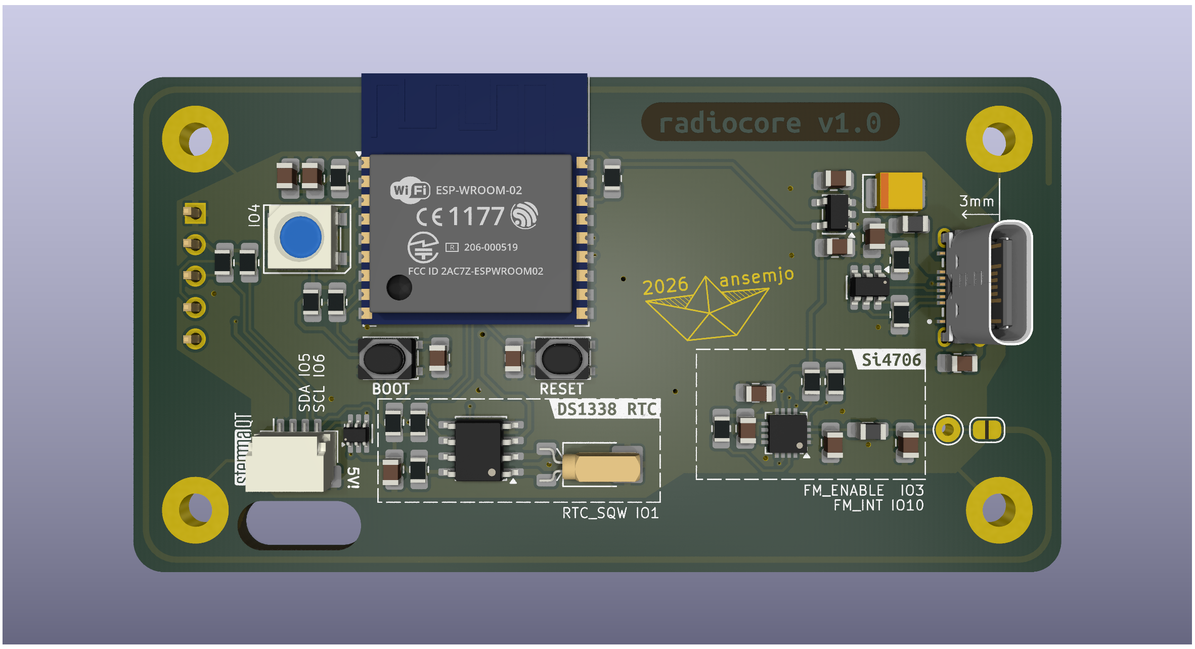
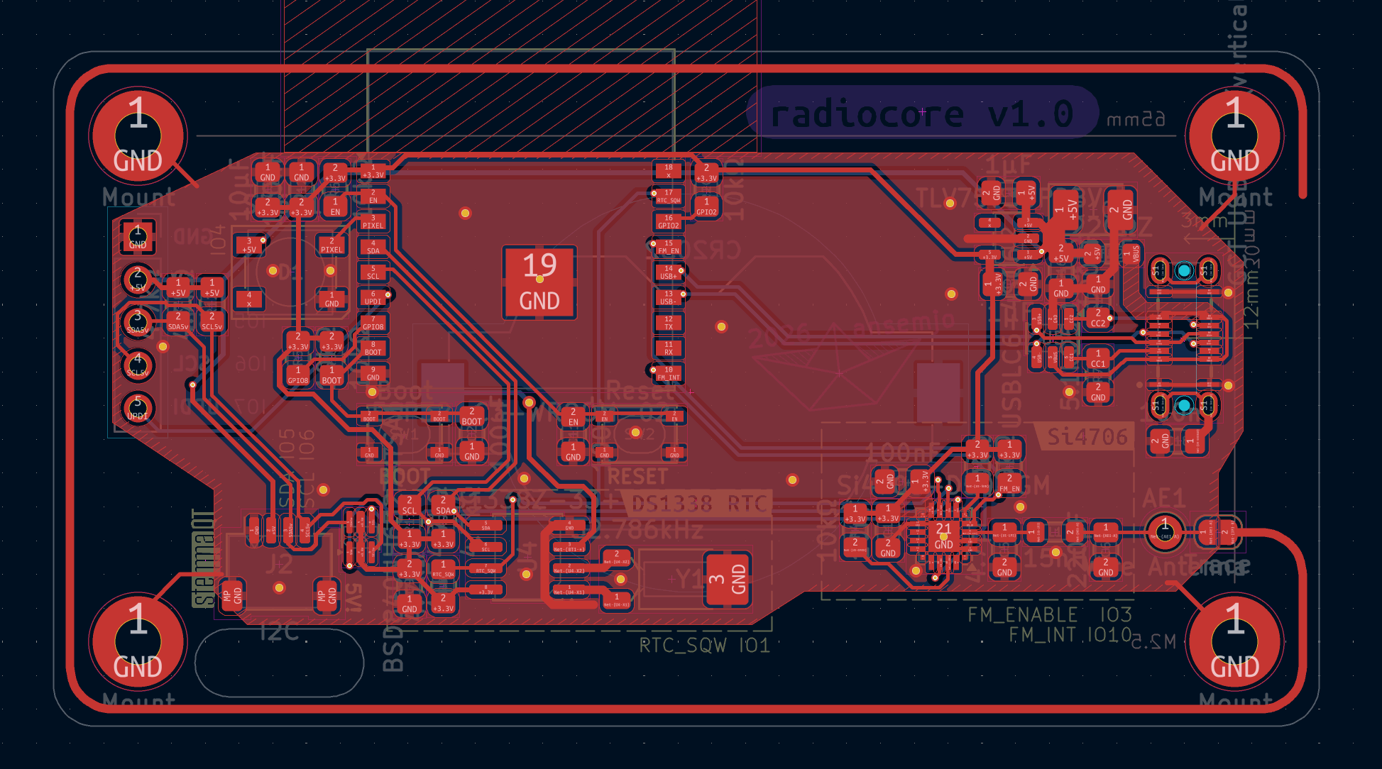
While the overall function works (reception is even better than expected, to be honest), I also made a few major mistakes:
The Neopixel is supplied with VBUS (~ 5V) but only gets logic level 3.3V on its data pin from the ESP32. When the VBUS supply voltage is slightly over 5V (like 5.2–5.3V), the Neopixel consistenly stays dark. When it is exactly at or slightly under 5V, you can sometimes get it to work. At 5V, the SK6812 requires a 3.6V logic level per the datasheet. Oops.
The UPDI connection (pin 5 on the side header) is connected directly to the ESP32 without level shifting or current limit. Since this pin is at 5V logic level on the ATtiny, you could damage the ESP32-C3 if it is ever connected during programming of the vfddriver. Use a Qwiic cable only or just solder the first four pins to be safe.
While it works out, the cutout under the Qwiic connector is a little close to properly insert the plug while the cable is already weaved through the hole.
In the previous vfddriver firmware, the display's address was 0x68 and thus collided with the RTC. I've moved the VFD to address 0x42 and you can still reconfigure it using the user_row, of course.
| Qty | Value | Footprint | References |
|---|---|---|---|
| 2 | 10kΩ | Resistor_SMD:R_0805_2012Metric_Pad1.20x1.40mm_HandSolder | R14, R15 |
| 2 | 10µH | Inductor_SMD:L_1210_3225Metric_Pad1.42x2.65mm_HandSolder | L1, L2 |
| 2 | 10Ω | Resistor_SMD:R_1206_3216Metric_Pad1.30x1.75mm_HandSolder | R16, R17 |
| 2 | 4.7µF | Capacitor_SMD:C_0805_2012Metric_Pad1.18x1.45mm_HandSolder | C1, C2 |
| 2 | Breadboard NC | Connector_PinHeader_2.54mm:PinHeader_1x02_P2.54mm_Vertical | J31, J32 |
| 2 | Breadboard Rail | Connector_PinHeader_2.54mm:PinHeader_1x02_P2.54mm_Vertical | J21, J22 |
| 1 | 10kΩ | Potentiometer_THT:Potentiometer_Bourns_3266W_Vertical | RV4 |
| 1 | 10nF | Capacitor_SMD:C_0805_2012Metric_Pad1.18x1.45mm_HandSolder | C11 |
| 1 | 10µF | Capacitor_SMD:C_0805_2012Metric_Pad1.18x1.45mm_HandSolder | C12 |
| 1 | 13kΩ | Resistor_SMD:R_0805_2012Metric_Pad1.20x1.40mm_HandSolder | R2 |
| 1 | 1N5819HW-7-F | Diode_SMD:D_SOD-123 | D1 |
| 1 | 2021 | ansemjo:ahoi | A1 |
| 1 | 240kΩ | Resistor_SMD:R_0805_2012Metric_Pad1.20x1.40mm_HandSolder | R3 |
| 1 | 47kΩ | Resistor_SMD:R_0805_2012Metric_Pad1.20x1.40mm_HandSolder | R1 |
| 1 | 47µF | Capacitor_SMD:CP_Elec_6.3x5.9 | C4 |
| 1 | 5V | TestPoint:TestPoint_THTPad_D1.5mm_Drill0.7mm | TP1 |
| 1 | 74LS132 | Package_SO:SOIC-14_3.9x8.7mm_P1.27mm | U1 |
| 1 | 82pF | Capacitor_SMD:C_0805_2012Metric_Pad1.18x1.45mm_HandSolder | C3 |
| 1 | Filament EN | Connector_PinHeader_2.54mm:PinHeader_2x01_P2.54mm_Vertical | J5 |
| 1 | Filament Jumper | Connector_PinHeader_2.54mm:PinHeader_2x02_P2.54mm_Vertical | J4 |
| 1 | G*** | kibuzzard-61E14426 | kibuzzard-61E14426 |
| 1 | GND | TestPoint:TestPoint_THTPad_D1.5mm_Drill0.7mm | TP4 |
| 1 | HV EN | Connector_PinHeader_2.54mm:PinHeader_2x01_P2.54mm_Vertical | J6 |
| 1 | HV Jumper | Connector_PinHeader_2.54mm:PinHeader_2x03_P2.54mm_Vertical | J3 |
| 1 | IVL2-5_7 | chronovfd:IVL2-7_5-singleSide | VFD1 |
| 1 | LM2733YMF | Package_TO_SOT_SMD:SOT-23-5 | U3 |
| 1 | PWR Header | Connector_PinHeader_2.54mm:PinHeader_2x02_P2.54mm_Vertical | J2 |
| 1 | Trimmer | Potentiometer_THT:Potentiometer_Bourns_3266W_Vertical | RV1 |
| 1 | USB_B_Micro | Connector_USB:USB_Micro-B_Amphenol_10118194_Horizontal | J1 |
| 1 | ZXBM5210-S | Package_SO:SOIC-8_3.9x4.9mm_P1.27mm | U4 |
| 1 | fA | TestPoint:TestPoint_THTPad_D1.5mm_Drill0.7mm | TP12 |
| 1 | fB | TestPoint:TestPoint_THTPad_D1.5mm_Drill0.7mm | TP11 |
| 1 | freq | TestPoint:TestPoint_THTPad_D1.5mm_Drill0.7mm | TP3 |
| 1 | hv | TestPoint:TestPoint_THTPad_D1.5mm_Drill0.7mm | TP2 |
ansemjo/chronovfd
hardware project for a clock around a russian ivl2-5/7 vfd and an esp32-wroom module

ansemjo/chronovfd
hardware project for a clock around a russian ivl2-5/7 vfd and an esp32-wroom module

ansemjo/chronovfd
hardware project for a clock around a russian ivl2-5/7 vfd and an esp32-wroom module

ansemjo/chronovfd
hardware project for a clock around a russian ivl2-5/7 vfd and an esp32-wroom module

ansemjo/chronovfd
hardware project for a clock around a russian ivl2-5/7 vfd and an esp32-wroom module

ansemjo/chronovfd
hardware project for a clock around a russian ivl2-5/7 vfd and an esp32-wroom module

ansemjo/chronovfd
hardware project for a clock around a russian ivl2-5/7 vfd and an esp32-wroom module


Artpel1805/Beerator
Le but du projet est de réaliser intégralement un robot capable de se déplacer, de chercher et d’attraper une canette (de bière ? 😶), relever sa couleur, puis de la déposer dans la zone de couleur correspondante.

cva68/ESPBreadboardRobot
Peripheral and breakout board for the ESP-32, with firmware designed for use with Microsoft MakeCode

It measures 51.7 × 33 mm and has 2 copper layers, 1.6 mm thick.
40 parts, built around the LM2733YMF, ZXBM5210-S, 74LS132P-E and LBC3225T100MR. The full list of its parts is on this page, with links to each part's symbol and footprint where PCBKit's library has them.
From the ansemjo/chronovfd repository on GitHub, at the commit this page was made from: the board is experiments/breadboard_psu/breadboard_psu.kicad_pcb and its schematic experiments/breadboard_psu/breadboard_psu.kicad_sch. PCBKit opens the board in the browser, with nothing to install.
Its repository publishes it under the CERN-OHL-P-2.0 licence: you may reuse it on that licence's terms (keep the author's notice, and for a copyleft licence share your changes alike).