L298N
akhil053/L298-Motor-Driver
This project focuses on the design of a DC motor driver PCB using the L298N motor driver IC. The schematic and PCB layout were developed in KiCad with proper component placement, routing, and net labeling.

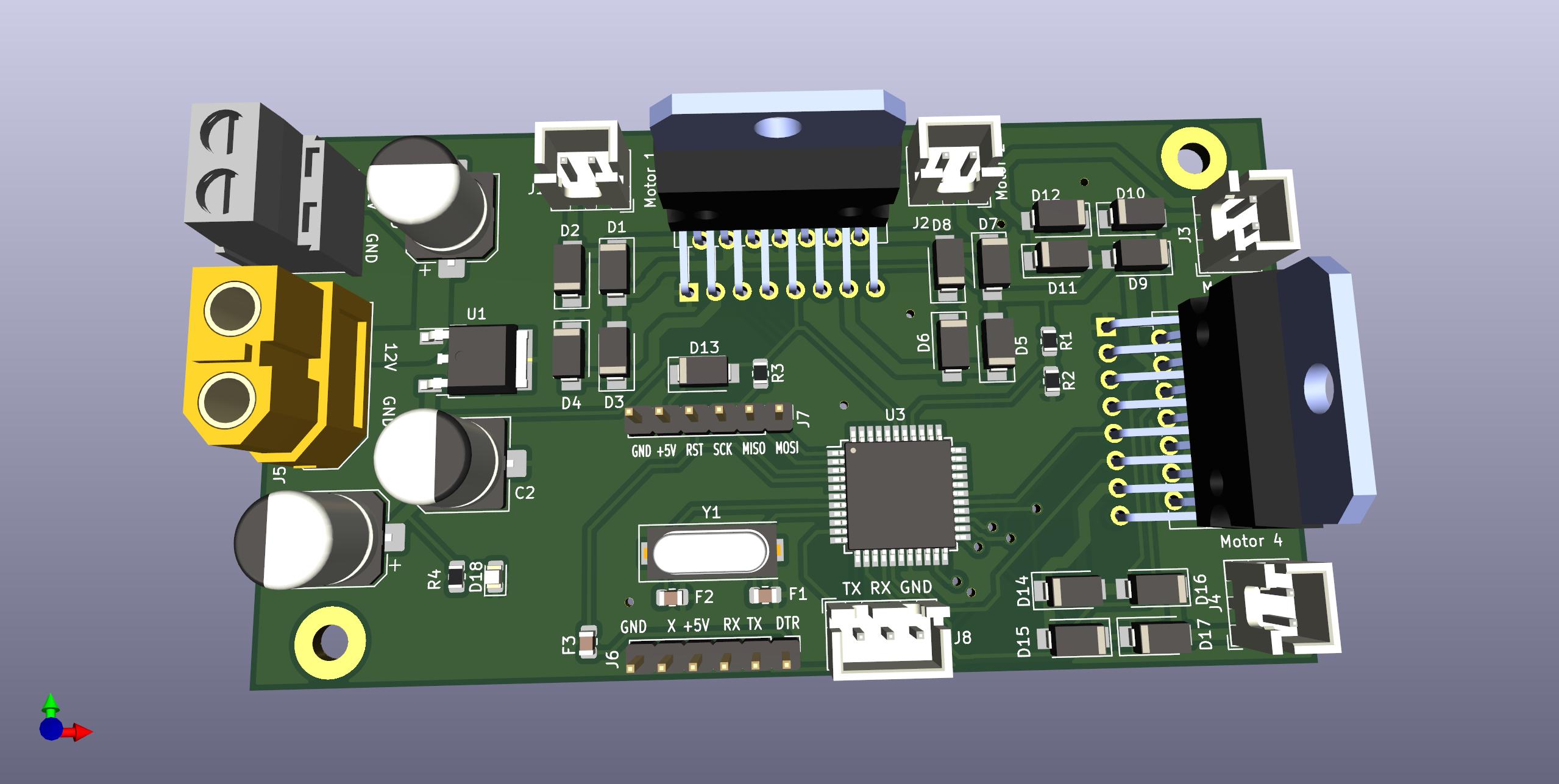
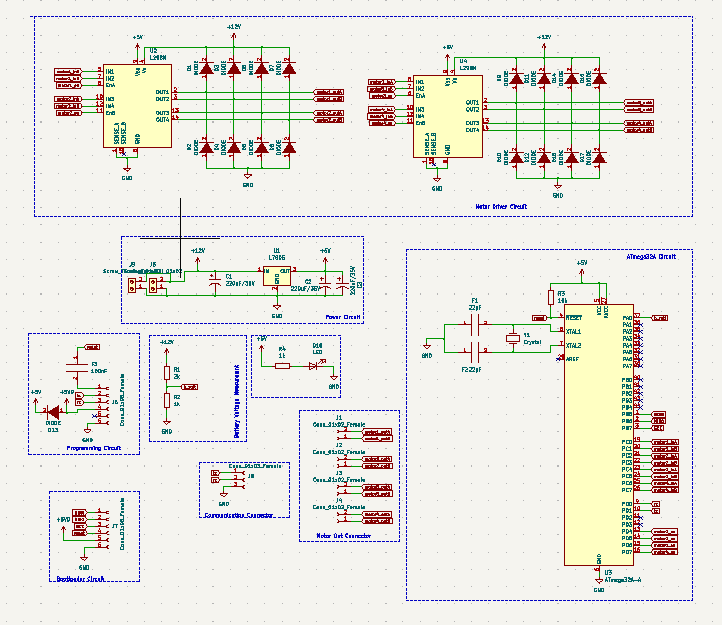
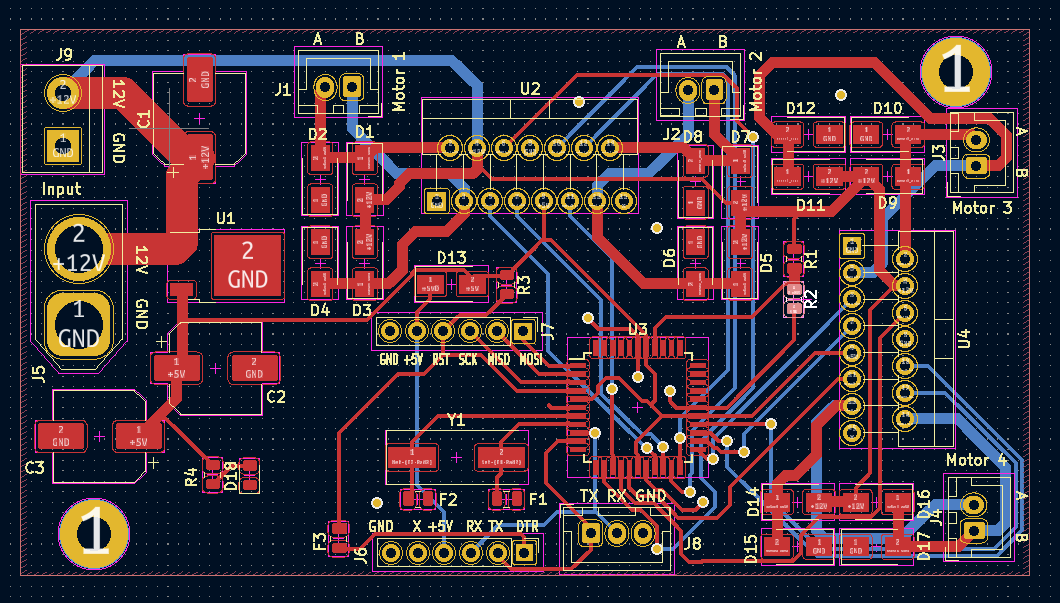
Motor driver arm is an open-source printed circuit board by angad-kumar, from the angad-kumar/motor_driver_pcb repository on GitHub. It is a 2-layer board of 96 × 52 mm with 44 parts on 53 nets, routed with 374 tracks and 20 vias.
It is built around the ATMEGA32A-AU, L298N and L7805. Its parts include 18 diodes, 9 connectors, 4 resistors, 4 ICs and 3 capacitors. It belongs with the robots and motor control boards and the AVR (ATmega, ATtiny) boards of this library.


| Qty | Value | Footprint | References |
|---|---|---|---|
| 17 | DIODE | Diode_SMD:D_SMA | D1, D2, D3, D4, D5, D6, D7, D8, D10, D11, D12, D13, D14, D15, D16, D17 +1 |
| 4 | Conn_01x02_Female | Connector_JST:JST_XH_B2B-XH-A_1x02_P2.50mm_Vertical | J1, J2, J3, J4 |
| 3 | 220uF/35V | Capacitor_SMD:CP_Elec_8x10.5 | C1, C2, C3 |
| 2 | 1k | Resistor_SMD:R_0805_2012Metric | R2, R4 |
| 2 | 22pF | Capacitor_SMD:C_0805_2012Metric | F1, F2 |
| 2 | Conn_01x06_Female | Connector_PinHeader_2.54mm:PinHeader_1x06_P2.54mm_Vertical | J6, J7 |
| 2 | L298N | Package_TO_SOT_THT:TO-220-15_P2.54x2.54mm_StaggerOdd_Lead4.58mm_Vertical | U2, U4 |
| 1 | 100nF | Capacitor_SMD:C_0805_2012Metric | F3 |
| 1 | 10k | Resistor_SMD:R_0805_2012Metric | R3 |
| 1 | 2k | Resistor_SMD:R_0805_2012Metric | R1 |
| 1 | ATmega32A-A | Package_QFP:TQFP-44_10x10mm_P0.8mm | U3 |
| 1 | Conn_01x03_Female | Connector_JST:JST_XH_B3B-XH-A_1x03_P2.50mm_Vertical | J8 |
| 1 | Crystal | Crystal:Crystal_SMD_HC49-SD | Y1 |
| 1 | L7805 | Package_TO_SOT_SMD:TO-252-2 | U1 |
| 1 | LED | LED_SMD:LED_0805_2012Metric | D18 |
| 1 | Screw_Terminal_01x02 | TerminalBlock:TerminalBlock_bornier-2_P5.08mm | J9 |
| 1 | Screw_Terminal_01x02 | Connector_AMASS:AMASS_XT60-F_1x02_P7.20mm_Vertical | J5 |
The 42 most common of 44 parts.

akhil053/L298-Motor-Driver
This project focuses on the design of a DC motor driver PCB using the L298N motor driver IC. The schematic and PCB layout were developed in KiCad with proper component placement, routing, and net labeling.


hurryharii/kicad-pcb-learning-project
A work-in-progress PCB designed using KiCad, featuring a 7805 voltage regulator, 1N4007 diodes, capacitors, motor connectors, and test points.


Mahfuz-Sarker136/L298N-Motor-driver-PCB-layout-with-Kicad
A custom, dual-layer L298N Motor Driver PCB module optimized for Robotics,Arduino or ESP-32 project


Omar-Hany00/ESP32-Robotic-Arm-Car
Custom ESP32-based RC robotic arm car with integrated PCB, motor control, and servo actuation.
It measures 96 × 52 mm and has 2 copper layers, 1.6 mm thick.
44 parts, built around the ATMEGA32A-AU, L298N and L7805. The full list of its parts is on this page, with links to each part's symbol and footprint where PCBKit's library has them.
From the angad-kumar/motor_driver_pcb repository on GitHub, at the commit this page was made from: the board is motor_driver_arm.kicad_pcb and its schematic motor_driver_arm.kicad_sch. PCBKit opens the board in the browser, with nothing to install.
Its repository states no licence, so its author keeps all rights: ask angad-kumar before reusing the design.