


2 layers50.6 × 75.1 mm

 andrewsargent2311-web/Engine_meter1
nRF52840 engine meter
Engine monitor V1 is an open-source printed circuit board by andrewsargent2311-web, from the andrewsargent2311-web/Engine_meter repository on GitHub, published under the GPL-3.0 licence. It is a 2-layer board with 44 parts on 49 nets.
It is built around the MAX31856, LMV331TP and BAT54W. Its parts include 15 resistors, 14 capacitors, 8 diodes, 4 ICs and 2 crystals. It belongs with the nRF52 and nRF5x boards of this library.
A small, battery-powered engine monitor for a paramotor. It measures RPM, CHT and EGT, and sends them over Bluetooth LE as NMEA-style sentences to Gaggle or the paraglide_vario_ESP32 flight computer. It also reports its own battery percentage.
It was designed and tested on a Moster 185 (single-cylinder two-stroke), but it should work on any engine with a spark-ignition lead and a thermocouple-instrumented head or exhaust.
| MCU | nice!nano (nRF52840) |
| RPM | Inductive pickup (2 wraps on the HT lead) → LMV331 comparator → interrupt |
| Temperature | Up to 2 × MAX31856 thermocouple amplifiers (CHT + EGT), K-type as shipped. The EGT channel is optional (see below) |
| Radio | BLE, Nordic UART Service, advertises as ParaEngineMeter |
| Update rate | 5 Hz |
| Power | 1000 mAh single-cell LiPo, JST-PH 2.0 mm, charged over USB-C |
| PCB | 2 layers, 1.6 mm, about 50.6 × 75.1 mm |
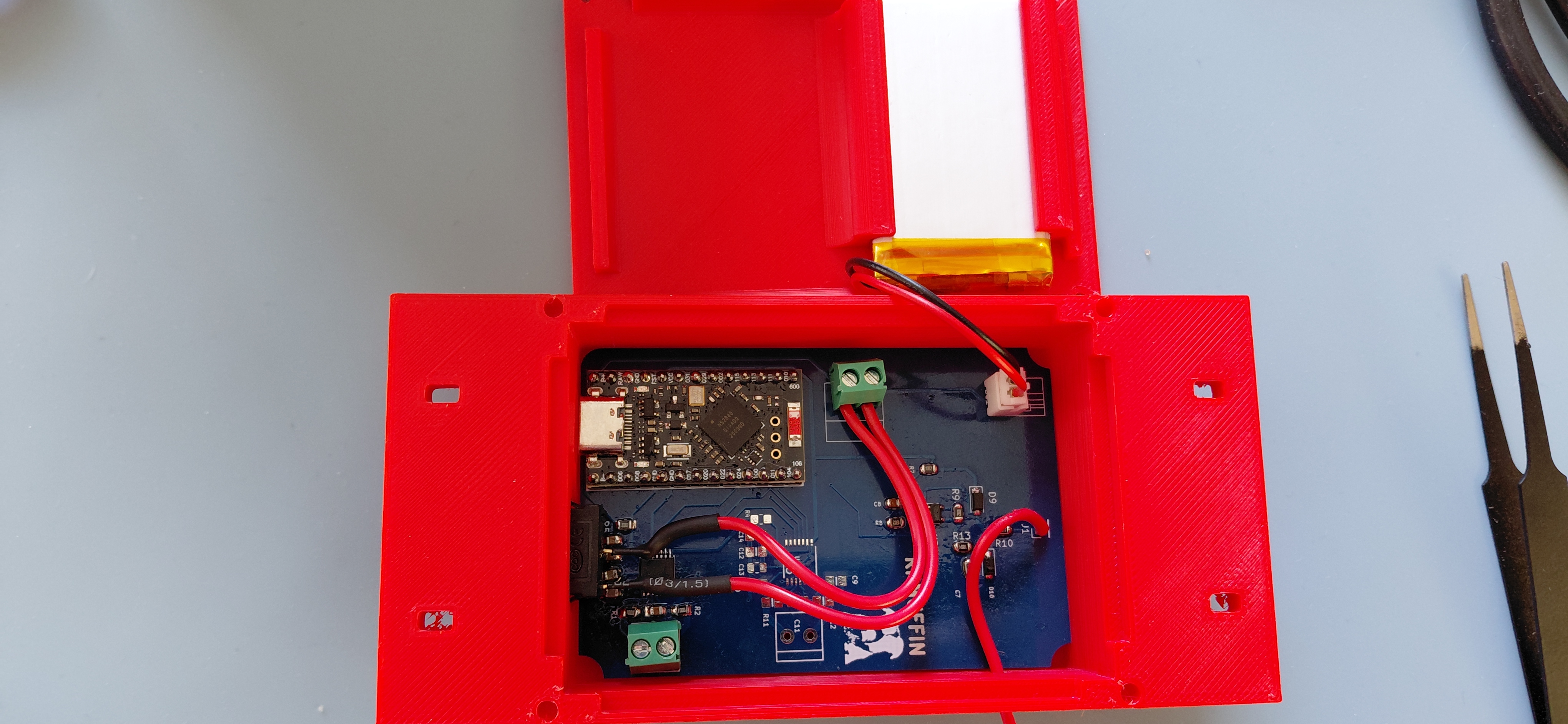
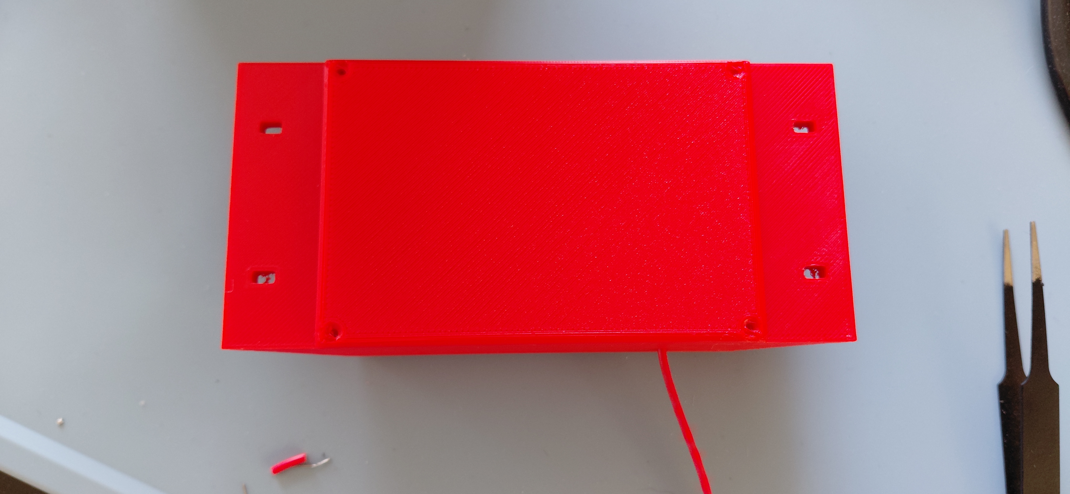
| Case | 3D printed (PLA), about 58.5 × 123.5 × 27 mm including mounting tabs |
| Path | Contents |
|---|---|
Engine_meter/ | PlatformIO firmware project (open this folder in VS Code) |
Engine_meter/src/ | main.cpp (RPM, thermocouples, BLE) and AuxSensors.cpp/.h (battery gauge) |
Engine_meter/boards/ | Custom nicenano board definition and pin variant for PlatformIO |
Engine_monitor_V1/ | KiCad 10 project: schematic and PCB |
Engine_monitor_V1/Gerber files/ | Fabrication outputs: Gerbers, drill files, JLCPCB BOM, JLCPCB CPL, and Engine_monitor_V1_order.zip |
3D print files/ | Case and lid as STL, plus ready-sliced G-code for a Prusa MK3S |
Photos/ | Photos of the bare PCB and the finished unit |
These are the parts in Engine_monitor_V1_BOM_JLCPCB.xlsx, and they can be assembled by JLCPCB.
| Qty | Value | Designators | Notes |
|---|---|---|---|
| 4 | 10 nF 50 V X7R | C1, C3, C9, C10 | Thermocouple input filtering |
| 7 | 100 nF 50 V X7R | C2, C4, C5, C8, C11, C12, C14 | Decoupling; C8 filters the comparator reference |
| 2 | 10 µF 25 V X5R | C6, C13 | 3.3 V bulk decoupling |
| 4 | 100 Ω 1 % | R1, R2, R11, R12 | Thermocouple input series resistors |
| 5 | 10 kΩ 1 % | R4, R5, R7, R8, R9 | R4/R5 chip-select pull-ups, R7/R8 comparator reference divider, R9 comparator output pull-up |
| 1 | 150 kΩ 1 % | R10 | RPM input series resistor. See the note below |
| 1 | 1 MΩ 1 % | R13 | Comparator hysteresis (positive feedback) |
| 1 | 220 kΩ 1 % | R14 | RPM input divider to GND |
| 2 | 1N5819HW-7-F Schottky, SOD-123 | D9, D10 | RPM input clamps (to 3.3 V and to GND) |
| 1 | LMV331IDBVR, SOT-23-5 | U2 | Single comparator |
| 2 | MAX31856MUD+, TSSOP-14 | U3, U4 | U3 = CHT, U4 = EGT. U4 is optional, see the note below |
R10 value: the production design uses 150 kΩ. It was originally 22 kΩ, which was too sensitive to pick up noise on the ignition lead, so it was increased. Use 150 kΩ.
EGT is optional: fitting an EGT probe usually means drilling and threading a hole in the exhaust, which can weaken it. Many builds therefore leave the EGT channel off (U4, the X2 terminal and that channel's input filter parts). Newer exhausts often ship with a threaded EGT port, in which case fit it. The firmware auto-detects whether U4 is present at power-up (see Optional thermocouple channels below), so the same firmware works either way.
D9/D10 in the JLCPCB BOM are marked "consigned" (you supply them). Either supply 1N5819HW-7-F parts yourself, or pick an in-stock SOD-123 Schottky at order time.
| Ref | Part | Purpose |
|---|---|---|
| U1 | nice!nano (v2 or compatible, nRF52840), 2 × 12-pin headers or castellated solder | MCU, BLE radio, LiPo charger |
| BT1 | JST-PH 2.0 mm 2-pin horizontal header (S2B-PH-K) | Battery connector |
| J2 | 2-pin screw terminal, 3.81 mm pitch (Phoenix MC 1,5/2-G-3.81 footprint) | Power switch (in series with the battery) |
| X1 | 2-pin screw terminal, 3.5 mm pitch | CHT thermocouple input |
| X2 | 2-pin screw terminal, 3.5 mm pitch | EGT thermocouple input |
| J1 | 1-pin 2.54 mm header (or a wire soldered straight in) | RPM pickup input |
Engine_monitor_V1/Gerber files/Engine_monitor_V1_order.zip.Engine_monitor_V1_BOM_JLCPCB.xlsx and Engine_monitor_V1_CPL_JLCPCB.csv. The BOM has no LCSC part numbers, so match each line to a stocked part in the JLCPCB parts picker (see the part table above). Only the SMD parts on the top side are assembled. You add the nice!nano, terminals, header and JST connector yourself.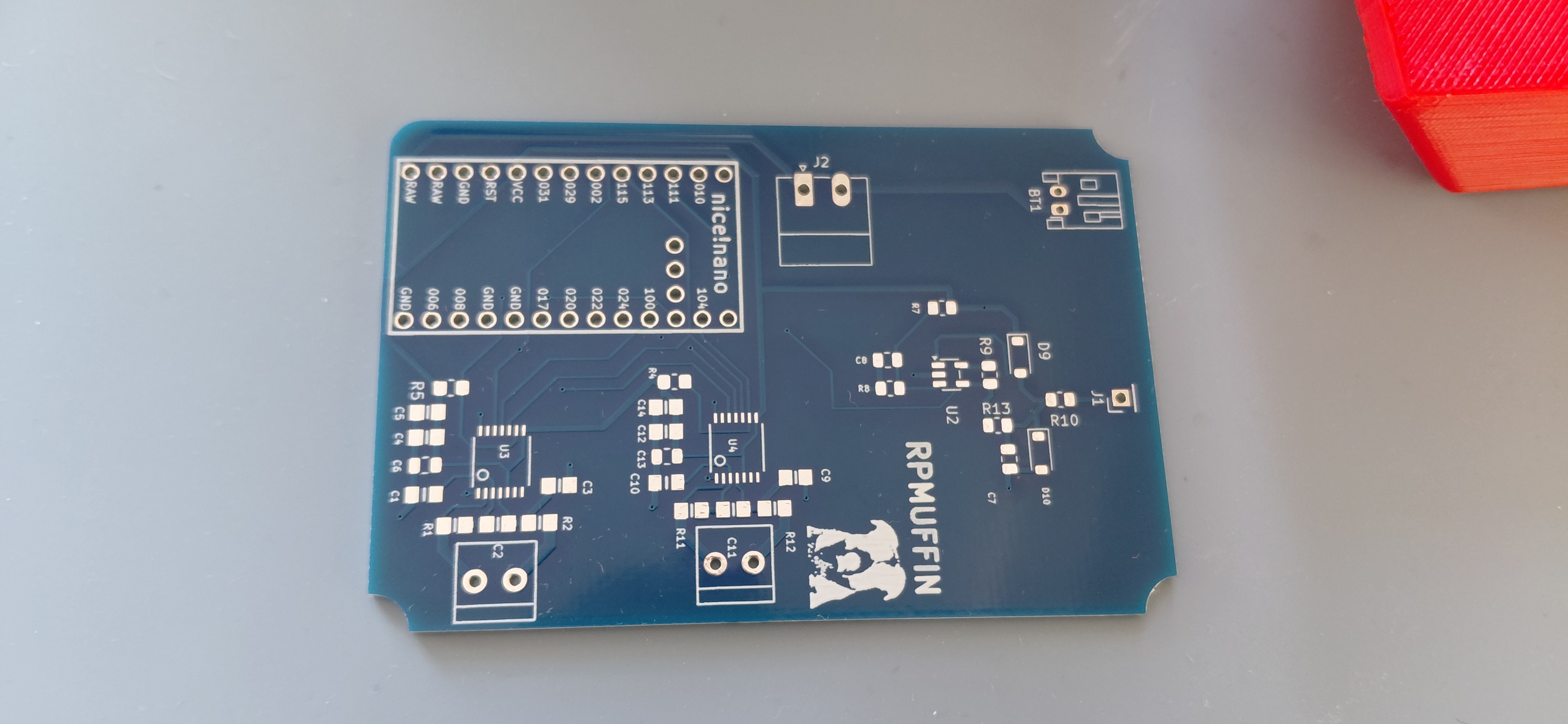
The two MAX31856 chips are TSSOP-14, so the SMD parts are best done with flux, a fine tip and a magnifier.
The firmware uses software (bit-banged) SPI, so the two MAX31856s share one bus with separate chip-selects.
| Signal | nice!nano GPIO | Firmware pin number |
|---|---|---|
| MAX31856 SDO → MCU (MISO) | P1.00 | 32 |
| MAX31856 SDI ← MCU (MOSI) | P1.13 | 45 |
| SCK | P1.15 | 47 |
| CS for CHT (U3) | P0.11 | 11 |
| CS for EGT (U4) | P1.04 | 36 |
| RPM comparator output | P1.11 | 43 |
Pin numbers follow the Adafruit nRF52 core convention: P0.xx → xx, P1.xx → 32 + xx.
Each channel copies the Adafruit MAX31856 breakout design: 100 Ω series resistors on the thermocouple inputs, 10 nF / 100 nF filtering, and a 10 kΩ pull-up on each chip-select. X1 = CHT (U3) and X2 = EGT (U4).
Polarity matters. If a reading falls when you warm the probe, swap the two wires. The firmware sets type K for both channels, but the MAX31856 supports B, E, J, K, N, R, S and T. To change it, edit the two setThermocoupleType(...) lines in setup() in Engine_meter/src/main.cpp.
⚠️ Check battery polarity before the first power-up. JST-PH LiPo packs from different suppliers are wired in different orders, and a reversed pack can destroy the nice!nano. Use a multimeter on the pack connector, and compare it with BT1 (pin 1 = +, pin 2 = GND) on the PCB. If it is reversed, re-pin the connector on the battery lead.
The firmware is a PlatformIO project in Engine_meter/.
Engine_meter folder (not the repo root).nordicnrf52 platform and the libraries (Adafruit MAX31856, BusIO and TinyUSB) on first build.VID_239A&PID_00B3), and the upload must target that port.The nicenano board definition in boards/ comes from ICantMakeThings/Nicenano-NRF52-Supermini-PlatformIO-Support via bertrik/nicenano-example.
At boot the firmware probes each MAX31856 by writing and reading back its thermocouple-type register. A missing chip cannot echo the values back, so that channel is marked not fitted and is reported as unavailable (99) in the $EMS sentence. The serial log at start-up shows [BOOT] CHT MAX31856: found, EGT MAX31856: not fitted, and the per-line output shows EGT=n/a.
Set CHT_PRESENCE / EGT_PRESENCE in main.cpp to TC_AUTO (default), TC_ABSENT (never read it) or TC_PRESENT (always read it, so a dead chip shows [FAULT] instead of vanishing). A chip that is fitted but has no probe attached is not "not fitted": it is detected, and reports a fault (open circuit) until a probe is connected.
Engine_meter/src/main.cpp)| Setting | Default | Meaning |
|---|---|---|
PULSES_PER_REV | 1.0 | Spark pulses per crank revolution. Correct for a single-cylinder two-stroke such as the Moster 185. If the reading is double or half what you expect, change this |
RPM_TIMEOUT_MS | 1500 | No pulse for this long → RPM reports 0 |
RPM_WINDOW_MS | 5000 | RPM averaging window |
RPM_FAST_ATTACK / RPM_FAST_WINDOW_MS / RPM_FAST_THRESHOLD | 1 / 1000 / 0.10 | Use a 1 s window when it differs from the 5 s average by more than 10 % |
RPM_ROUND_TO / RPM_HYST | 10 / 7.0 | Displayed RPM is rounded to 10 RPM with 7 RPM hysteresis |
RPM_MIN_LOCKOUT_US | 5000 | Ignores edges closer together than this (ringing rejection). It adapts to 40 % of the last period above about 600 RPM |
CHT_PRESENCE / EGT_PRESENCE | TC_AUTO | TC_AUTO, TC_PRESENT or TC_ABSENT. See Optional thermocouple channels |
TC_FAULT_HOLD_COUNT | 3 | A temperature is only reported unavailable after this many consecutive bad reads. Until then the last good value is re-sent, hiding single glitches from ignition noise |
TC_WARMUP_MS | 500 | Readings are ignored this long after power-up while the first conversion completes |
WATCHDOG_TIMEOUT_MS | 8000 | The MCU resets itself if the main loop stalls this long. 0 disables the watchdog |
PEMBAT_INTERVAL_MS | 1000 | How often the battery sentence is sent |
SEND_PEMBAT | 1 | Set to 0 to stop sending the proprietary battery sentence |
RPM_DEBUG_EDGES | 0 | Set to 1 to print raw edge intervals when diagnosing pickup noise |
The device advertises as ParaEngineMeter and exposes the Nordic UART Service. Each message is an ASCII sentence with an XOR checksum and CRLF line ending.
$EMS,<pressure>,<fuelFlow>,<fuelRemaining>,<fuelUsed>,<ambientTemp>,<CHT>,<EGT>,<waterTemp>,<RPM>*HH
$PEMBAT,<percent>*HHEMS fields are filled with 999999 (pressure), 9999 (fuel fields) or 99 (temperatures).99 means unavailable (sensor fault, no probe, or that channel's chip is not fitted).0 is a valid stopped-engine reading.$PEMBAT is battery percentage, 0–100, estimated from the nRF52840's internal supply-voltage ADC and a single-cell LiPo curve. It is approximate. It reads high while charging and sags under load.Example: RPM 3100, CHT 180.0 °C, EGT 550.0 °C:
$EMS,999999,9999,9999,9999,99,18000,55000,99,310000*7CGaggle: add the meter under Profile → Equipment → Bluetooth Devices. Gaggle must receive a real supported reading within about 35 seconds.
paraglide_vario_ESP32: select ParaEngineMeter in the vario's Bluetooth scan list.
The case and lid are in 3D print files/.
| File | Print time (Prusa MK3S, 0.15 mm, PLA) |
|---|---|
Engine meter case.stl | 5 h 18 min |
Engine meter lid.stl | 1 h 44 min |
Ready-sliced G-code for a Prusa MK3S is included. For another printer, slice the STLs yourself, 0.15 mm layers in PLA or similar (PETG is a better choice for a hot, sunny harness).
If RPM is wrong: no reading means add a turn, and spurious readings mean remove a turn or move the wrap further from the plug. The rejects counter in the serial output shows how many noise edges are being filtered. The reading is also wrong if PULSES_PER_REV doesn't match your engine.
Connect a switch to J2, plug the battery into BT1 (after checking polarity), and charge through the nice!nano's USB-C port.
[BOOT] Engine meter ready, advertising as ParaEngineMeter.n/a. With a probe attached you should see room temperature. Warm the probe and check that the reading rises.BAT= value is sensible for the pack voltage.$EMS sentences arrive.This project is open source under the GNU General Public License v3.0. See LICENSE for the full text. It covers the firmware, PCB design files, case models and documentation in this repository. You are free to build, modify and share it, and if you distribute a modified version you must release your changes under the same license.
Third-party files keep their own licenses and notices (see Credits below).
| Qty | Value | Footprint | References |
|---|---|---|---|
| 6 | 0.1uF | Adafruit MAX31856:0805-NO | C2, C4, C5, C11, C12, C14 |
| 6 | 10K | Adafruit MAX31856:0805-NO | R3, R4, R5, R13, R14, R15 |
| 6 | 1N4148 | Adafruit MAX31856:SOD-323 | D1, D2, D3, D4, D7, D8 |
| 4 | 100 | Adafruit MAX31856:0805-NO | R1, R2, R11, R12 |
| 3 | 10k | Resistor_SMD:R_0805_2012Metric | R7, R8, R9 |
| 2 | 0.01uF | Adafruit MAX31856:0805-NO | C3, C9 |
| 2 | 0.01uF | Adafruit MAX31856:0805_10MGAP | C1, C10 |
| 2 | 10u | Capacitor_SMD:C_0805_2012Metric | C6, C13 |
| 2 | 3.5mm term | Adafruit MAX31856:TERMBLOCK_1X2-3.5MM | X1, X2 |
| 2 | BAT54W | Diode_SMD:D_SOD-123 | D5, D6 |
| 2 | MAX31856 | Adafruit MAX31856:TSSOP14 | U3, U4 |
| 1 | 100nF | Capacitor_SMD:C_0805_2012Metric | C8 |
| 1 | 10nF | Capacitor_SMD:C_0805_2012Metric | C7 |
| 1 | 1M | Resistor_SMD:R_0805_2012Metric | R10 |
| 1 | 22k | Resistor_SMD:R_0805_2012Metric | R6 |
| 1 | LMV331 | Package_TO_SOT_SMD:SOT-23-5 | U2 |
| 1 | RPM_PICKUP | Connector_PinHeader_2.54mm:PinHeader_1x01_P2.54mm_Vertical | J1 |
| 1 | nice_nano | nice-nano-kicad-master:nice_nano | U1 |


takuhoTech/CelestNavi-Combo
Ready-to-use GNSS+CLAS receiver with integrated loop antenna


mariusenglund/three-phase-inverter
Materials for enhancing the DC-to-AC converter that was designed as part of our bachelor's thesis in the spring of 2023.

lucasbaizer/pico-2v
RP2354A development board with switchable voltage, QSPI breakout, and more

ajisrawi/sentinel-uhf-radar
Reference design of a two-face UHF early-warning phased-array radar: system sizing, MoM antenna simulation, seven KiCad PCB projects, Blender site model


44 parts, built around the MAX31856, LMV331TP and BAT54W. The full list of its parts is on this page, with links to each part's symbol and footprint where PCBKit's library has them.
From the andrewsargent2311-web/Engine_meter repository on GitHub, at the commit this page was made from: the board is Engine_monitor_V1/_restore_backup_2026-09-02T17-29-26-343/Engine_monitor_V1.kicad_pcb and its schematic Engine_monitor_V1/Engine_monitor_V1.kicad_sch. PCBKit opens the board in the browser, with nothing to install.
Its repository publishes it under the GPL-3.0 licence: you may reuse it on that licence's terms (keep the author's notice, and for a copyleft licence share your changes alike).