4 layers83 × 53.5 mm
ESP 32 PCB Project
BBIkal/ESP32_IOT_Project
A compact 4-layer mixed-signal PCB designed in KiCad 9, built around the ESP32-C3 module for IoT sensor applications.
92 parts

 andrewcnjuguna/ESP32_BME690
Multi-room ESP32-S3 environmental sensor node that streams air-quality data to a Node.js server over Wi-Fi. Built around the Bosch BME690 with auxiliary light, sound and battery monitoring.
ESP32 BME690 is an open-source printed circuit board by andrewcnjuguna, from the andrewcnjuguna/ESP32_BME690 repository on GitHub. It is a 4-layer board of 108.5 × 60 mm with 98 parts on 101 nets, routed with 1,073 tracks and 117 vias.
It is built around the ESP32-S3-WROOM-1-N8, MCP73871EV and BME690, with the MAX4466EXK+T, W25Q32JVSSIQ and GSD090012SEU among its other parts. Its parts include 38 resistors, 28 capacitors, 8 ICs, 6 diodes and 5 connectors. It belongs with the ESP32 boards of this library.


Multi-room ESP32-S3 environmental sensor node that streams air-quality data to a Node.js server over Wi-Fi. Built around the Bosch BME690 with auxiliary light, sound and battery monitoring.
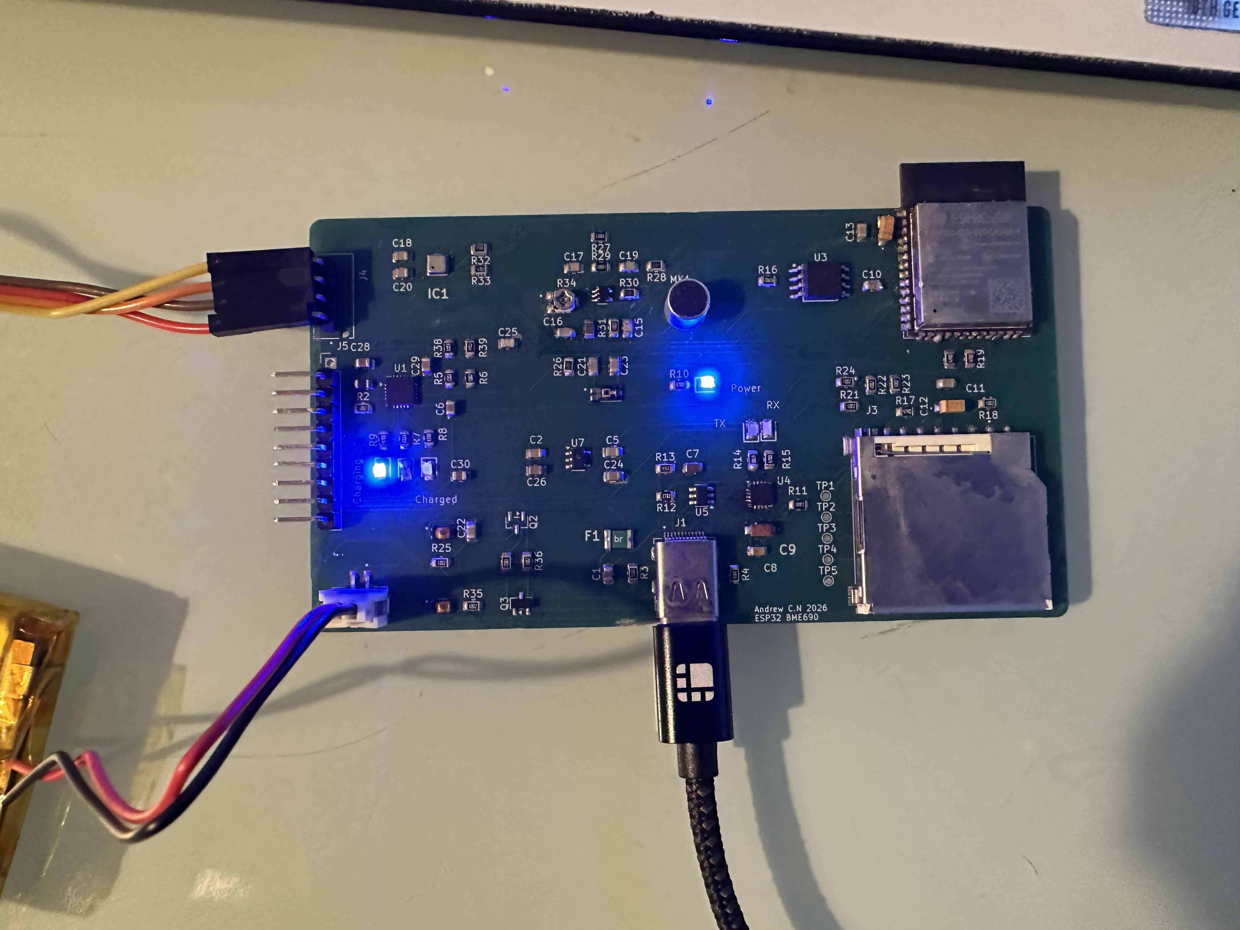
KiCad project lives in hardware/kicad/.
| Function | GPIO |
|---|---|
| I2C SDA | 8 |
| I2C SCL | 9 |
| Status LED | 2 |
| Light sensor (TEMT6000) | 5 |
| Microphone | 4 |
| VBAT sense | 1 |
Sketches live in firmware/.
ESP32_BME690_usb/ — main node firmwarebattery_level/, light_sensor_test/, sound_sensor/ — bring-up sketchesfirmware/ESP32_BME690_usb/ in the Arduino IDE.secrets.h.example → secrets.h and fill in your Wi-Fi credentials
and server URL. secrets.h is gitignored.Adafruit GFX, Adafruit SH110X,
BSEC2 (Bosch), ArduinoJson, ArduinoOTA.locationID constant in the sketch tags this node's
data on the server (e.g. Kitchen, Living_Room).Each node runs its own tiny status page at http://<node-ip>/
(auto-refreshes every 5 s). It shows the live BSEC readings, light / sound /
battery, WiFi signal (RSSI in dBm, an approximate 0–100 % quality, and a
label Excellent/Good/Fair/Weak/Poor), and the SD-log status. If the SD card
is mounted it also links http://<node-ip>/datalog.csv to download the full
log.
The node's IP is printed on the serial console at boot
([INFO] Web UI at http://...).
WiFi is self-healing: if the router is down at boot (or the link drops later), the node keeps logging to SD and retries the connection every 30 s in the background; OTA and the web page start automatically as soon as the first connection succeeds — no reboot needed.
Every 3 s BSEC cycle the node POSTs a JSON snapshot to SERVER_URL
(/sensor-data on the dashboard server). The payload includes location,
all sensor channels, and the WiFi link quality (rssi in dBm plus a derived
wifiPercent). Nodes running older firmware simply omit the WiFi fields —
the dashboard shows "not reported (update firmware)" for them.
A small Node/Express app in server/ collects POSTs from each node and serves a per-room dashboard.
cd server
npm install express
node server.js
Then point a browser at http://<host>:3000.
POST /sensor-data — nodes push their JSON snapshot here.GET /data — latest snapshot of every room, as JSON.GET / — dashboard. Room boxes are created dynamically from whatever
location tags have reported, so adding a node needs no server change.
Each box shows the air-quality channels plus battery and WiFi signal
quality for that node.The pi_server notes file documents the systemd / iptables setup used on
the home Raspberry Pi.
The node averages its 3 s BSEC samples and appends one CSV row per minute
to /datalog.csv on the SD card:
boot_id,uptime_s,epoch,synced,temp_c,hum_pct,press_hpa,iaq,iaq_acc,
co2_ppm,voc_ppm,lux,sound_db,sound_avg,sound_peak,batt_v,batt_pct
boot_id — power-session counter (persisted in EEPROM), groups rows from
one uninterrupted run.uptime_s — seconds since boot (monotonic, rollover-safe).epoch / synced — Unix time and whether NTP had synced when the row was
written. Rows logged before the sync have epoch=0, but their true time
is still recoverable (see below).iaq_acc — BSEC accuracy 0–3; air-quality values below your chosen
threshold are warm-up noise.Grab the file over WiFi from http://<node-ip>/datalog.csv, or pull the
card.
analysis/plot_datalog.pypip install pandas matplotlib
python analysis/plot_datalog.py datalog.csv # plot a local file
python analysis/plot_datalog.py --ip 192.168.0.65 # fetch straight from the node
python analysis/plot_datalog.py datalog.csv -o out.png # save instead of showing
python analysis/plot_datalog.py datalog.csv --last 48 # last 48 h only
python analysis/plot_datalog.py datalog.csv --min-accuracy 3 # strict AQ filterThe script produces six stacked, time-aligned panels: temp+humidity, pressure, IAQ, CO₂eq+VOCeq, light+sound, and battery. Under the hood it:
boot_id it derives
boot_epoch = epoch − uptime_s from the NTP-synced rows, then stamps
every row of that session as boot_epoch + uptime_s — so even rows
logged before the NTP sync get correct timestamps. Sessions that never
synced have no time anchor and are dropped with a warning.iaq_acc < --min-accuracy (default 1) so BSEC's calibration period
doesn't draw misleading flat lines.--gap-min (default 5 min) means the node was off; a NaN break is
inserted so downtime shows as a blank gap instead of a false straight
line across it.firmware/ Arduino sketches (main + bring-up)
server/ Node/Express dashboard
analysis/ plot_datalog.py — CSV log plotting
hardware/ KiCad project + design notes
images/ PCB photosComponent datasheets are kept locally only (not redistributable).
| Qty | Value | Footprint | References |
|---|---|---|---|
| 13 | 0.1u | Capacitor_SMD:C_0805_2012Metric | C2, C5, C8, C10, C11, C13, C15, C17, C18, C20, C22, C23, C25 |
| 13 | 10k | Resistor_SMD:R_0805_2012Metric | R2, R18, R21, R22, R23, R24, R25, R26, R31, R35, R36, R37, R39 |
| 6 | 10u | Capacitor_SMD:C_0805_2012Metric | C1, C6, C26, C28, C29, C30 |
| 6 | 470 | Resistor_SMD:R_0805_2012Metric | R7, R8, R9, R10, R14, R15 |
| 4 | 47 | Resistor_SMD:R_0805_2012Metric | R16, R17, R19, R20 |
| 3 | 1k | Resistor_SMD:R_0805_2012Metric | R11, R27, R29 |
| 3 | LTST-C170KRKT | ESP32 Project Footprints:LEDC2012X120N | LED1, LED4, LED6 |
| 2 | 10n | Capacitor_SMD:C_0805_2012Metric | C19, C21 |
| 2 | 10u | ESP32 Project Footprints:T491A | C12, C14 |
| 2 | 1M | Resistor_SMD:R_0805_2012Metric | R28, R30 |
| 2 | 1u | Capacitor_SMD:C_0805_2012Metric | C7, C27 |
| 2 | 4k7 | Resistor_SMD:R_0805_2012Metric | R32, R33 |
| 2 | 5k1 | Resistor_SMD:R_0805_2012Metric | R3, R4 |
| 2 | BC817 | Package_TO_SOT_SMD:SOT-23 | Q2, Q3 |
| 2 | LTST-C170GKT | ESP32 Project Footprints:LEDC2012X120N | LED2, LED5 |
| 2 | USLPT2819DT2TR | ESP32 Project Footprints:SW_USLPT2819DT2TR | S1, S2 |
| 1 | 0ZCH0110AF2E | ESP32 Project Footprints:FUSC3226X100N | F1 |
| 1 | 100k | Resistor_SMD:R_0805_2012Metric | R38 |
| 1 | 100p | Capacitor_SMD:C_0805_2012Metric | C16 |
| 1 | 20k | Resistor_SMD:R_0805_2012Metric | R5 |
| 1 | 22k1 | Resistor_SMD:R_0805_2012Metric | R12 |
| 1 | 22u | Capacitor_SMD:C_0805_2012Metric | C24 |
| 1 | 2k | Resistor_SMD:R_0805_2012Metric | R6 |
| 1 | 35WR100KLFTR | ESP32 Project Footprints:TRIM_35WR100KLFTR | R34 |
| 1 | 4.7u | ESP32 Project Footprints:T491A | C9 |
| 1 | 47k5 | Resistor_SMD:R_0805_2012Metric | R13 |
| 1 | AP2112K-3.3 | Package_TO_SOT_SMD:SOT-23-5 | U7 |
| 1 | B2B-PH-SM4-TB | ESP32 Project Footprints:JST_B2B-PH-SM4-TB | J2 |
| 1 | B4B-XH-AM__LF__SN_ | ESP32 Project Footprints:JST_B4B-XH-AM__LF__SN_ | J4 |
| 1 | BME690 | ESP32 Project Footprints:BME690 | IC1 |
| 1 | CMC-5042PF-AC | ESP32 Project Footprints:CUI_CMC-5042PF-AC | MK1 |
| 1 | CP2102N-Axx-xQFN20 | Package_DFN_QFN:SiliconLabs_QFN-20-1EP_3x3mm_P0.5mm_EP1.8x1.8mm | U4 |
| 1 | Conn_01x10_Pin | Connector_PinHeader_2.54mm:PinHeader_1x10_P2.54mm_Vertical | J5 |
| 1 | ESP32-S3-WROOM-1 | RF_Module:ESP32-S3-WROOM-1 | U2 |
| 1 | FBMJ2125HM330-T | ESP32 Project Footprints:BEADC2012X105N | FB1 |
| 1 | GSD090012SEU | ESP32 Project Footprints:AMPHENOL_GSD090012SEU | J3 |
| 1 | LTST-C170TBKT | ESP32 Project Footprints:LEDC2012X120N | LED3 |
| 1 | MAX4466EXK | ESP32 Project Footprints:SOT65P210X110-5N | U6 |
| 1 | MCP73871 | Package_DFN_QFN:QFN-20-1EP_4x4mm_P0.5mm_EP2.5x2.5mm | U1 |
| 1 | SS-52400-002 | ESP32 Project Footprints:BELFUSE_SS-52400-002 | J1 |
| 1 | TEMT6000X01 | ESP32 Project Footprints:TRANS_TEMT6000X01 | Q1 |
| 1 | Test CLK | TestPoint:TestPoint_Pad_D1.0mm | TP3 |
| 1 | Test CS | TestPoint:TestPoint_Pad_D1.0mm | TP5 |
| 1 | Test CS_SD | TestPoint:TestPoint_Pad_D1.0mm | TP4 |
| 1 | Test MISO | TestPoint:TestPoint_Pad_D1.0mm | TP2 |
| 1 | Test MOSI | TestPoint:TestPoint_Pad_D1.0mm | TP1 |
| 1 | USBLC6-2SC6 | Package_TO_SOT_SMD:SOT-23-6 | U5 |
| 1 | W25Q32JVSSIQ | ESP32 Project Footprints:SOIC127P790X216-8N | U3 |
BBIkal/ESP32_IOT_Project
A compact 4-layer mixed-signal PCB designed in KiCad 9, built around the ESP32-C3 module for IoT sensor applications.

KirtiChickamath/ESP32-IoT-sensor-board
ESP32- IoT sensor board. 4-layer PCB, designed in KiCad . Features LiPo charging, USB-C, SPI flash, SD card, BME280, and more.

chopda15/ESP32-sensor-board
Custom-designed ESP32-C3 IoT PCB with integrated Li-ion charging, environmental sensing, data logging, USB-C connectivity, and power-efficient embedded system architecture.


WasikeIsaac/ESP32_IOT-PCB-
ESP32 IoT board: 4-layer KiCad PCB with USB-C, BME280, mic, audio amp, SD card, GPIO breakout. Full custom design from schematic to layout.


Kaushalyasamantha/ESP32-C3-IoT-Dev-Board
"A custom 4-layer IoT development board built around the ESP32-C3 in KiCad 9"

pasensiojimenez/esp32-sensor-board
4-layer ESP32-C3 IoT development board designed in KiCad 10. Onboard power management (USB-C/LiPo), environmental sensors (BME280, light, sound), and SD/flash storage.
It measures 108.5 × 60 mm and has 4 copper layers, 1.6 mm thick.
98 parts, built around the ESP32-S3-WROOM-1-N8, MCP73871EV, BME690 and MAX4466EXK+T. The full list of its parts is on this page, with links to each part's symbol and footprint where PCBKit's library has them.
From the andrewcnjuguna/ESP32_BME690 repository on GitHub, at the commit this page was made from: the board is hardware/kicad/ESP32_BME690.kicad_pcb and its schematic hardware/kicad/ESP32_BME690.kicad_sch. PCBKit opens the board in the browser, with nothing to install.
Its repository states no licence, so its author keeps all rights: ask andrewcnjuguna before reusing the design.