2 layers57 × 55.2 mm
LogicAnalyzer
gusmanb/logicanalyzer
24 channel, 100Msps logic analyzer hardware and software
10 parts5.1kGPL-3.0
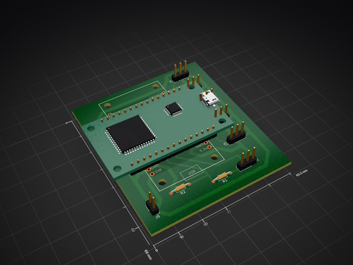
 andcoderes/Chopper-Head
Chopper head firmware — servo animations, NeoPixel effects, web dashboard, encrypted ESP-NOW
Chopper Head is an open-source printed circuit board by andcoderes, from the andcoderes/Chopper-Head repository on GitHub. It is a 2-layer board of 60.5 × 68 mm with 10 parts on 30 nets, routed with 86 tracks and 0 vias.
Its parts include 7 connectors and 2 resistors.
This firmware was strongly influenced by the Amidala firmware by thePunderWoman.
Firmware for Chopper (C1-1OP) head built on the ESP32-WROOM-32. Controls servo animations, RGB LED lighting effects, and communicates wirelessly with a main controller via ESP-NOW.
| Component | Details |
|---|---|
| Microcontroller | ESP32-WROOM-32 |
| Servo controller | Pololu Maestro (UART2, GPIO 16 TX / GPIO 17 RX) |
| Left jewel eye | NeoPixel, 7 pixels, GPIO 4 |
| Right jewel eye | NeoPixel, 7 pixels, GPIO 18 |
| Center eye | NeoPixel, 1 pixel, GPIO 5 |
| Ladder | NeoPixel, 11 pixels, GPIO 19 |
| Periscope | NeoPixel, 1 pixel, GPIO 2 |
PCB design files are in the PCB/ directory.
src/
  main.cpp                    Entry point and main loop
  config.h                    Pin definitions, MAC addresses (keys come from secrets.h)
  lights/                     LED control (JewelEye, Ladder, PixelLight, LightController)
  servo/                      Pololu Maestro servo scripts
  communication/              ESP-NOW receiver and message types
  web/                        Embedded web server, logging, serial buffer
include/
  web_pages.h                 Auto-generated embedded HTML (built by scripts/embed_web.py)
  secrets.h                   Auto-generated ESP-NOW keys (built by scripts/load_secrets.py), gitignored
web/                          Web UI source files (HTML, CSS)
test/                         Unit tests and hardware mocks
scripts/
  embed_web.py                Pre-build script that inlines web assets into firmware
  load_secrets.py             Pre-build script: .env -> include/secrets.h
partitions/
  ota_4MB.csv                 OTA partition table
PCB/                          PCB design and CNC routing files
.env.example Template for ESP-NOW keys — copy to .envembed_web.py and load_secrets.py build scripts)Clone the repository and open it in VS Code.
Set up .env — see Generating ESP-NOW keys below. This covers PMK_KEY/LMK_KEY, CONTROLLER_MAC, and WIFI_AP_PASSWORD. The build fails with a clear error if .env is missing.
Optionally edit src/config.h:
WIFI_AP_SSID if desired.Build the firmware:
pio run -e esp32devUpload to the ESP32:
pio run -e esp32dev -t uploadOpen the serial monitor:
pio device monitor -b 115200Connect to the ChopperHead WiFi access point, then open one of:
http://chopper.headhttp://chopper.localhttp://192.168.5.2| Page | Description |
|---|---|
| Home | Device info — firmware version, MAC address, uptime, heap memory, ESP-NOW status |
| Serial Monitor | Real-time log viewer with command buttons and macro sender |
| Firmware Update | OTA upload with progress tracking |
| Endpoint | Method | Description |
|---|---|---|
/api/info | GET | Device telemetry (JSON) |
/api/monitor | GET | Live log stream (JSON) |
/api/command | POST | Send button or macro commands |
| Button | Action |
|---|---|
| Y | Toggle arms in/out |
| X | Say hi (both arms) |
| B | Say hi (left arm) |
| D-pad Up | Periscope up |
| D-pad Down | Periscope down |
| D-pad Left/Right | Periscope animation |
| Macro ID | Effect |
|---|---|
| 101 | Red eye animation |
| 103 | Periscope up sequence |
| 107 | Custom animation |
The head communicates with the controller using packed structs over ESP-NOW:
HeadCommand (controller → head): button presses, macro sequences, volume, idle mode, and connection status.
HeadTelemetry (head → controller): connection state, animation status, and uptime. Sent every 1 second.
Connection is considered lost after 5 seconds without data.
Unit tests run on the native platform (no hardware required):
pio test -e nativeTests cover: LightController, ServoController, ESP-NOW controller, JewelEye, PixelLight, MessageTypes, and startup animation.
This board talks to the other Chopper boards over encrypted ESP-NOW. Before
your first build, generate two 16-byte (128-bit) keys — a Primary Master Key
(PMK) and a Local Master Key (LMK) — and put them in a .env file
(gitignored, never commit it) at the project root:
cp .env.example .envGenerate two random 16-byte keys, each as 32 hex characters:
# Option 1: openssl
openssl rand -hex 16   # run twice — once for PMK_KEY, once for LMK_KEY

# Option 2: python
python3 -c "import secrets; print(secrets.token_hex(16))"
Edit .env and paste the values in:
PMK_KEY=<first random hex string>
LMK_KEY=<second random hex string>
These two keys must be byte-for-byte identical across chopper body,
chopper head, and chopper receiver — generate them once and copy the same
.env values into all three projects. Mismatched keys mean the boards can't
decrypt each other's ESP-NOW packets and the mesh will never connect.
.env also holds CONTROLLER_MAC — the controller's WiFi MAC address (as
hex, e.g. C0CDD6CA29E0), which must likewise be identical across all three
firmware projects — and WIFI_AP_PASSWORD, the password for this board's
local OTA-update access point (pick your own, at least 8 characters; unlike
the other values, this one doesn't need to match the other boards).
scripts/load_secrets.py runs automatically before every build (see
platformio.ini) and turns .env into include/secrets.h, which
config.h includes. Neither .env nor the generated secrets.h are
committed to git.
All rights reserved.
| Qty | Value | Footprint | References |
|---|---|---|---|
| 1 | 1K | Resistor_THT:R_Axial_DIN0204_L3.6mm_D1.6mm_P7.62mm_Horizontal | R1 |
| 1 | 2K | Resistor_THT:R_Axial_DIN0204_L3.6mm_D1.6mm_P7.62mm_Horizontal | R2 |
| 1 | Power In | Connector_PinHeader_2.54mm:PinHeader_1x02_P2.54mm_Vertical | J6 |
| 1 | RX/TX/GND | Connector_PinHeader_2.54mm:PinHeader_1x03_P2.54mm_Vertical | J8 |
| 1 | center_eye | Connector_PinHeader_2.54mm:PinHeader_1x03_P2.54mm_Vertical | J3 |
| 1 | ladder | Connector_PinHeader_2.54mm:PinHeader_1x03_P2.54mm_Vertical | J4 |
| 1 | left_eye | Connector_PinHeader_2.54mm:PinHeader_1x03_P2.54mm_Vertical | J1 |
| 1 | periscope pixel | Connector_PinHeader_2.54mm:PinHeader_1x03_P2.54mm_Vertical | J5 |
| 1 | right_eye | Connector_PinHeader_2.54mm:PinHeader_1x03_P2.54mm_Vertical | J2 |
| 1 | ~ | custom:ESP32_30pin | chopper_head1 |
It measures 60.5 × 68 mm and has 2 copper layers, 1.6 mm thick.
10 parts. The full list of its parts is on this page, with links to each part's symbol and footprint where PCBKit's library has them.
From the andcoderes/Chopper-Head repository on GitHub, at the commit this page was made from: the board is PCB/Chopper_head/Chopper_head.kicad_pcb and its schematic PCB/Chopper_head/Chopper_head.kicad_sch. PCBKit opens the board in the browser, with nothing to install.
Its repository states no licence, so its author keeps all rights: ask andcoderes before reusing the design.
gusmanb/logicanalyzer
24 channel, 100Msps logic analyzer hardware and software

byrantech/laptop
anyon_e, a highly integrated, high end, open source laptop. Attempt the impossible.

joeycastillo/Sensor-Watch
A board replacement for the classic Casio F-91W wristwatch


OLIMEX/OLINUXINO
OLINUXINO is Open Source / Open Hardware, low cost from EUR 24 Linux Industrial grade Single Board Computer capable to operate -25+85C

rusefi/rusefi
rusefi - GPL internal combustion engine control unit

VoronDesign/Voron-Hardware
Cool Hardware designed by the Voron Design group

hoglet67/RGBtoHDMI
Bare-metal Raspberry Pi project that provides pixel-perfect sampling of Retro Computer RGB/YUV video and conversion to HDMI