
4 layers99.6 × 76.2 mm

 anadskman/Automatic-Soldering-Helper
A small robot arm that can help hold wires, PCBs and other parts while I'm soldering.
Automatic Soldering Helper is an open-source printed circuit board by anadskman, from the anadskman/Automatic-Soldering-Helper repository on GitHub. It is a 2-layer board of 97.8 × 72.4 mm with 18 parts on 32 nets, routed with 147 tracks and 6 vias.
It is built around the ULN2003. Its parts include 5 switches, 3 connectors, 1 capacitor, 1 resistor and 1 IC. It belongs with the robots and motor control boards of this library.
A small robot arm that can help hold wires, PCBs and other parts while I'm soldering.
I wanted to make something like a motorised helping hand that I can move around with buttons instead of having to keep adjusting normal helping hands every time.
I already had most of the motors and electronics so I decided to try make the arm mostly out of parts I already had.
The whole arm rotates around the base using a 28BYJ-48 stepper motor and a ULN2003 driver.
The rest of the arm uses 4 small 9g servos:
I originally planned on using a gear ratio for the base because I thought the stepper might struggle with the weight of the arm.
After printing most of the arm and seeing how light it actually was I decided to remove the whole gear ratio part and just attach the motor directly to the arm. This also makes the base way simpler and smaller.
Before buying the final electronics I printed everything for the arm except the final motor base and connected it to an Arduino Uno just to confirm the idea would actually work.
I only have 3 potentiometers so for testing I used them to control the servos and switched between the wrist and clamp when needed.
Kinda surprisingly it worked pretty well.
There is a small bit of electrical noise making the servos vibrate but I'm adding a 1000uF capacitor to the final electronics which should help with that.
The Arduino is only being used for testing. The final version will use an ESP32.
I printed a small basic clamp for the first test just to make sure the servo could actually open and close something.
After that I redesigned it into a bigger clamp taking inspiration from some videos I saw on Instagram.
The bigger one should be much more useful for actually holding wires, connectors and small PCBs so I think I'll use that for the final version.
The clamp is controlled by another 9g servo.
I wanted the final arm to use physical controls instead of needing a computer every time I want to move it.
I'm using:
The potentiometers can be used to manually position the shoulder, elbow and wrist.
The buttons can then be used for things like:
The ESP32 can save arm positions so I can move the arm somewhere useful and then return to that position later without manually adjusting everything again.
A saved position can store:
This means I could have different positions for stuff like holding wires or holding a PCB.
The positions will be stored on the ESP32 so they don't disappear every time it loses power.
The base uses the 28BYJ-48 stepper motor I already had.
I originally designed a larger base with printed gears to increase the torque but after actually printing the arm it was much lighter than I expected.
Because of that I decided to remove the gears and just drive the rotating part directly from the stepper.
There will also be a limit switch so the arm can find its home position when it starts.
For attaching the whole thing to my desk I'm going to reuse the clamp from my old helping hands.
It already works well for attaching stuff to the edge of a table so there isn't much point designing another clamp.
The helping hands clamp will just slot into a mount on the bottom of the arm.
The final controller will be an ESP32 CH340C USB-C development board.
The servos aren't going to be powered directly from the ESP32.
They will use the 5V power rail and all of the grounds will be connected together.
I'm also adding a 1000uF capacitor across the servo power to help with the small amount of electrical noise I noticed while testing.
The stepper motor will be controlled through its ULN2003 board.
I don't really need a normal manufactured PCB for this project so I'm making a 3D printed one instead.
The PCB will basically have slots and paths where I can insert the wires to keep everything organised.
I redesigned the PCB after working out the final electronics and made sure to export the traces in the STEP this time because I forgot to last time and ended up drawing them by hand in Fusion.
The ESP32 and other electronics can then mount onto this inside the case.
The final firmware will run on the ESP32.
Instead of using GRBL I decided to make the position system specifically for the arm since only the base uses a stepper and everything else uses servos.
The firmware will handle:
This should make it pretty easy to use while I'm actually soldering instead of having to control it from my computer.
| Item | Qty | Status | Price | Notes |
|---|---|---|---|---|
| ESP32-CH340C-Type-C | 1 | Buy | $5.03 | Main controller |
| 1000uF 50V Electrolytic Capacitors | 5 | Buy | $2.22 | Servo power smoothing |
| M2 Hex Socket Button Head Screw Kit | 1 | Buy | $6.99 | Arm assembly |
| DS228/DS428 12mm Green Momentary Pushbuttons | 6 | Buy | $3.25 | Physical controls |
| 28BYJ-48 5V Stepper Motor | 1 | Owned | $0.00 | Rotates the arm |
| ULN2003 Stepper Driver Board | 1 | Owned | $0.00 | Drives the stepper |
| 9g Servo | 4 | Owned | $0.00 | Shoulder, elbow, wrist and clamp |
| 10k Potentiometer | 3 | Owned | $0.00 | Manual arm controls |
| Limit Switch | 1 | Owned | $0.00 | Base homing |
| 10k Resistor | 1 | Owned | $0.00 | Limit switch pull-up |
| Cost | |
|---|---|
| Subtotal | $17.56 |
| Savings | -$0.19 |
| Shipping | $0.00 |
| Estimated import charges | $16.93 |
| Total | $34.30 |
So far I've:
The main thing now is getting the final parts and putting everything together properly.
| Schematic | PCB | Case |
|---|---|---|
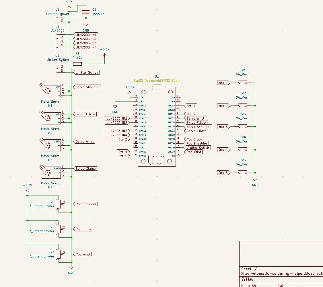 | 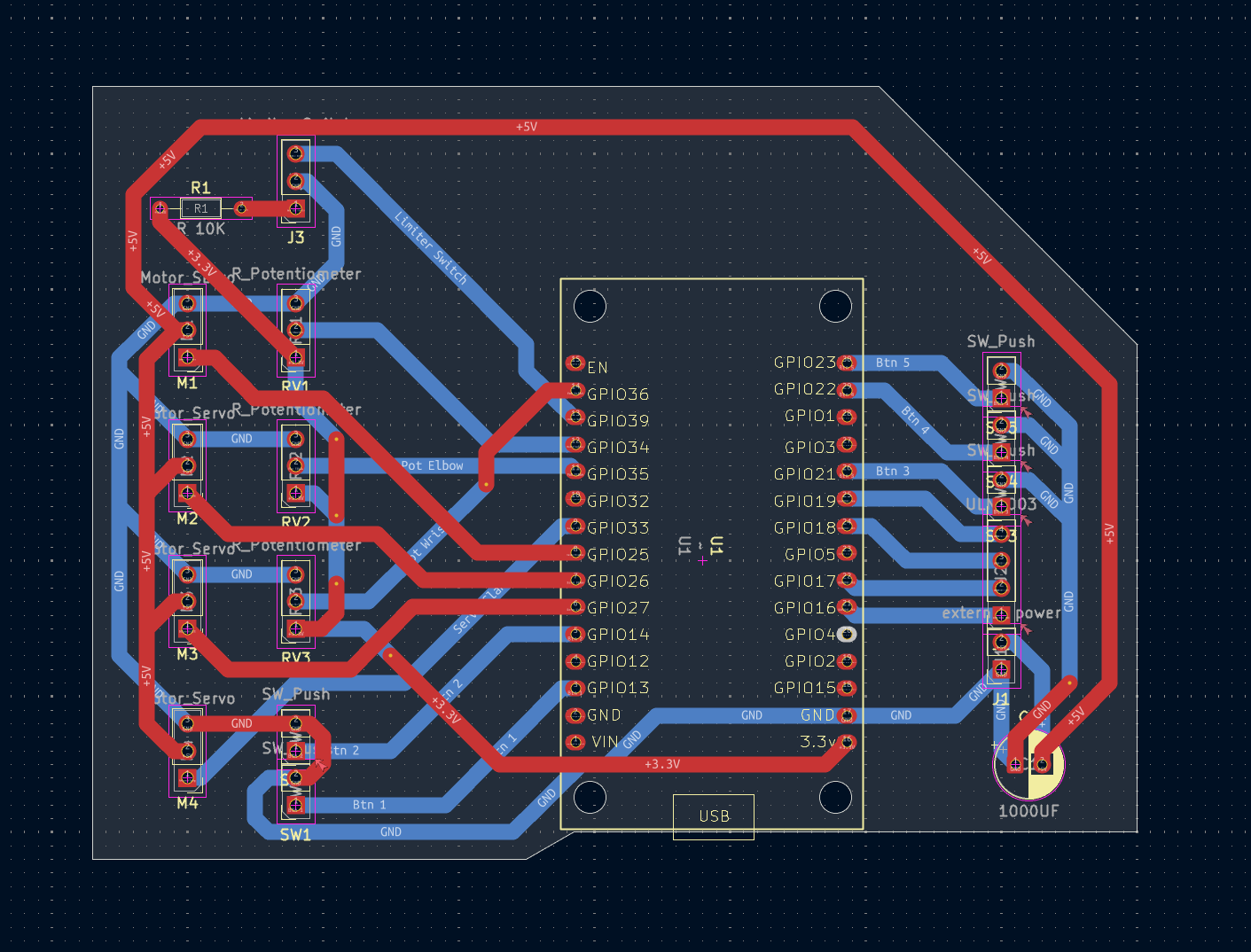 | 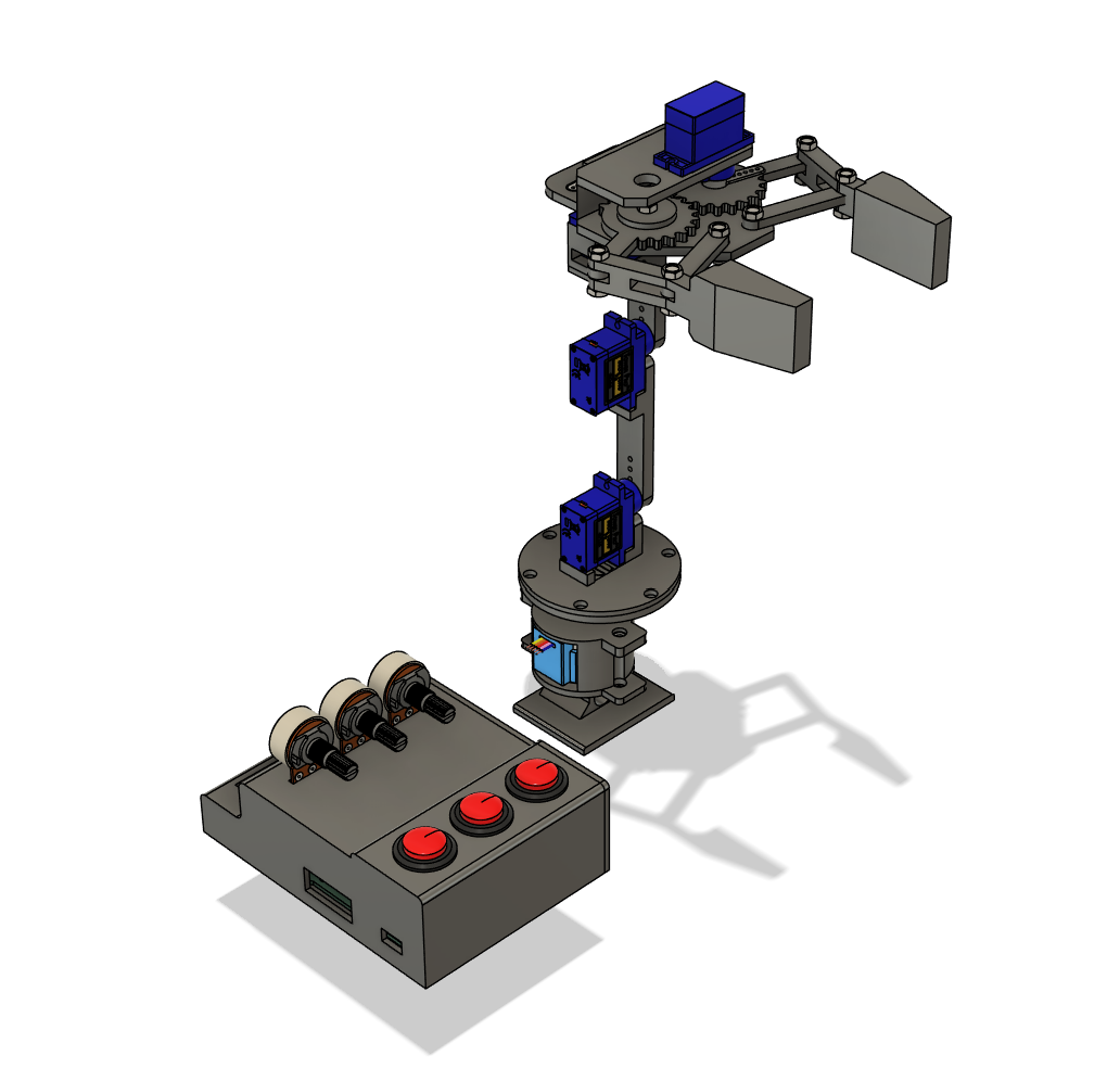 |
| Qty | Value | Footprint | References |
|---|---|---|---|
| 5 | SW_Push | Connector_PinSocket_2.54mm:PinSocket_1x02_P2.54mm_Vertical | SW1, SW2, SW3, SW4, SW5 |
| 4 | Motor_Servo | Connector_PinHeader_2.54mm:PinHeader_1x03_P2.54mm_Vertical | M1, M2, M3, M4 |
| 3 | R_Potentiometer | Connector_PinSocket_2.54mm:PinSocket_1x03_P2.54mm_Vertical | RV1, RV2, RV3 |
| 1 | 1000UF | Capacitor_THT:CP_Radial_D6.3mm_P2.50mm | C1 |
| 1 | Limiter Switch | Connector_PinSocket_2.54mm:PinSocket_1x03_P2.54mm_Vertical | J3 |
| 1 | R 10K | Resistor_THT:R_Axial_DIN0204_L3.6mm_D1.6mm_P7.62mm_Horizontal | R1 |
| 1 | ULN2003 | Connector_PinSocket_2.54mm:PinSocket_1x04_P2.54mm_Vertical | J2 |
| 1 | external power | Connector_PinSocket_2.54mm:PinSocket_1x02_P2.54mm_Vertical | J1 |
| 1 | ~ | Esp32 Devboard:ESP32_30pin | U1 |

jmfriedt/SDR-GB-SAR
Opensource, openhardware implementation of a Software Defined Radio (SDR) Ground Based Synthetic-Aperture RADAR (GB-SAR)

tnn85/MPCNC-Nano-Estlcam-Shield
Ein CNC Shield für die MPCNC in Verwendung mit Estlcam

jlecomte/ascom-oag-focuser
Open Source ASCOM-Compatible OAG Focuser For Astrophotography


TheYoctoJester/dutler
A bench butler for your Device Under Test: turns a Raspberry Pi Pico into a USB-serial console bridge with power-relay and MOSFET strap/reset control for embedded-Linux bring-up and hardware-in-the-loop.

terjeio/CNC_Breakout_Nucleo64
CNC breakout for STM324F411 and ST32F446 development boards
It measures 97.8 × 72.4 mm and has 2 copper layers, 1.6 mm thick.
18 parts, built around the ULN2003. The full list of its parts is on this page, with links to each part's symbol and footprint where PCBKit's library has them.
From the anadskman/Automatic-Soldering-Helper repository on GitHub, at the commit this page was made from: the board is PCB/Automatic-soldering-helper.kicad_pcb and its schematic PCB/Automatic-soldering-helper.kicad_sch. PCBKit opens the board in the browser, with nothing to install.
Its repository states no licence, so its author keeps all rights: ask anadskman before reusing the design.