2 layers57 × 55.2 mm
LogicAnalyzer
gusmanb/logicanalyzer
24 channel, 100Msps logic analyzer hardware and software
10 parts5.1kGPL-3.0
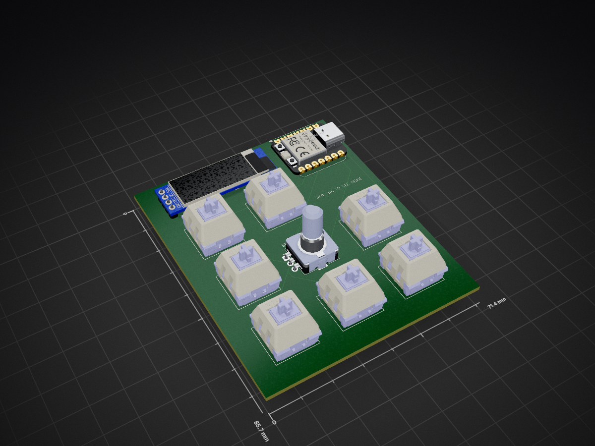
 AM1NOM/Controla
Controla is a compact, tactile controller that brings your most-used shortcuts and actions within reach.
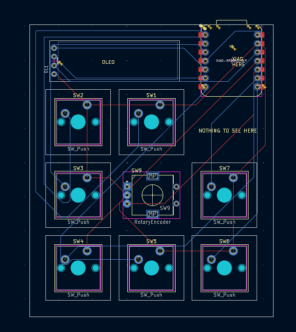
Hackpad is an open-source printed circuit board by AM1NOM, from the AM1NOM/Controla repository on GitHub, published under the MIT licence. It is a 2-layer board of 71.4 × 85.7 mm with 10 parts on 14 nets, routed with 74 tracks and 0 vias.
Its parts include 8 switches and 1 IC. It belongs with the RP2040 boards of this library.
Controla is a compact, tactile controller that brings your most-used shortcuts and actions within reach. It pairs responsive physical controls with a crisp OLED for clear status and feedback, so you always know what layer or mode you’re in. Perfect for switching tools, controlling media, or speeding up repetitive tasks, Controla fits neatly beside your keyboard and adapts to your workflow.
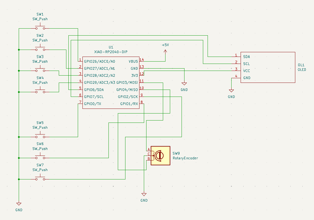
Schematic:
PCB:
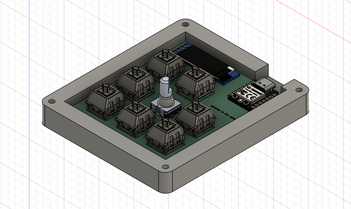
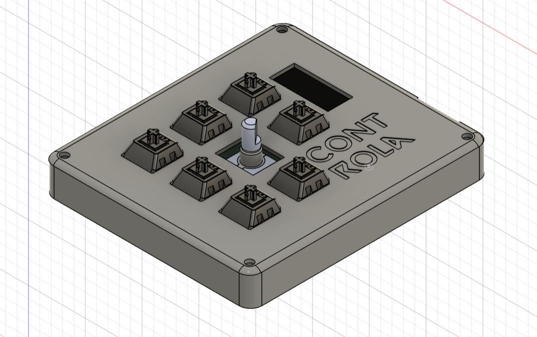
CAD:
| Ref | Qty | Part | Description |
|---|---|---|---|
| U1 | 1 | Seeed XIAO RP2040 (SMD) | RP2040 MCU module, SMD mount |
| OLED1 | 1 | 0.91" OLED SSD1306 I2C | Pin order GND-VCC-SCL-SDA |
| ENC1 | 1 | EC11 Rotary Encoder w/ push | Volume / scroll encoder |
| KNOB1 | 1 | Encoder knob | Fits EC11 shaft |
| SW1-SW7 | 7 | MX-style mechanical switches | Keyboard switches |
| KEYCAPS | 7 | Blank DSA keycaps (white) | For MX switches |
| LED1-LED7 | 7 | SK6812 MINI-E RGB LEDs | Per-key RGB lighting |
| D1-D7 | 7 | 1N4148 diodes (TH) | Optional, for key matrix |
| PCB1 | 1 | Custom PCB | Macropad PCB |
| M3x16 | 4 | M3 x 16mm screws | Case mounting |
| HEATSET | 4 | M3 heatset inserts | For 3D printed case |
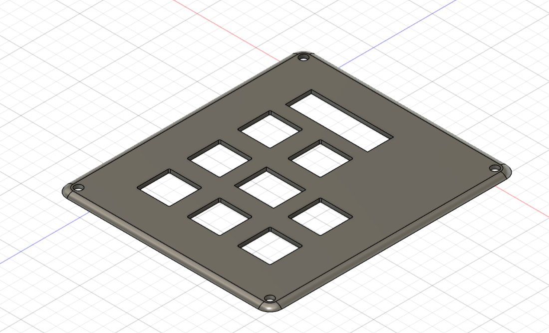
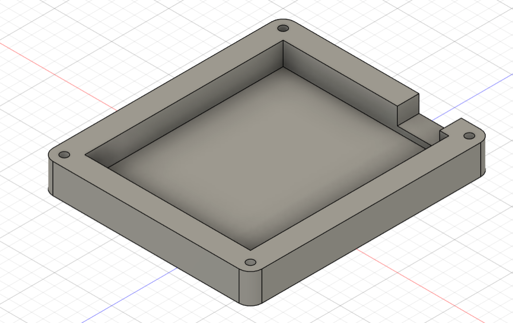
| CASE | 1 | 3D printed case | No acrylic |
| SOLDER_IRON | 1 | Soldering iron | Required for assembly |
| SOLDER | 1 | Solder wire 0.5mm | For TH + SMD |
| FLUX | 1 | Flux pen | Recommended for SMD |
For the complete, raw BOM file see BOM.csv.
Firmware and microcontroller code are in Firmware/main.py.
PCB/ folderCAD/ folderThis project is open-source.
| Qty | Value | Footprint | References |
|---|---|---|---|
| 7 | SW_Push | Button_Switch_Keyboard:SW_Cherry_MX_1.00u_PCB | SW1, SW2, SW3, SW4, SW5, SW6, SW7 |
| 1 | OLED | OLEDS:OLED | OL1 |
| 1 | RotaryEncoder | Rotary_Encoder:RotaryEncoder_Alps_EC11E_Vertical_H20mm | SW9 |
| 1 | XIAO-RP2040-DIP | OPL:XIAO-RP2040-DIP | U1 |
It measures 71.4 × 85.7 mm and has 2 copper layers, 1.6 mm thick.
10 parts. The full list of its parts is on this page, with links to each part's symbol and footprint where PCBKit's library has them.
From the AM1NOM/Controla repository on GitHub, at the commit this page was made from: the board is PCB/hackpad.kicad_pcb and its schematic PCB/OPL_Kicad_Library-master/Grove Vision AI V2 Library/Grove - Vision AI Module V2.kicad_sch. PCBKit opens the board in the browser, with nothing to install.
Its repository publishes it under the MIT licence: you may reuse it on that licence's terms (keep the author's notice, and for a copyleft licence share your changes alike).
gusmanb/logicanalyzer
24 channel, 100Msps logic analyzer hardware and software

byrantech/laptop
anyon_e, a highly integrated, high end, open source laptop. Attempt the impossible.

joeycastillo/Sensor-Watch
A board replacement for the classic Casio F-91W wristwatch


OLIMEX/OLINUXINO
OLINUXINO is Open Source / Open Hardware, low cost from EUR 24 Linux Industrial grade Single Board Computer capable to operate -25+85C

rusefi/rusefi
rusefi - GPL internal combustion engine control unit

VoronDesign/Voron-Hardware
Cool Hardware designed by the Voron Design group

hoglet67/RGBtoHDMI
Bare-metal Raspberry Pi project that provides pixel-perfect sampling of Retro Computer RGB/YUV video and conversion to HDMI