
2 layers152.4 × 101.6 mm
8088-FE2010A SBC
skiselev/micro_8088
Micro 8088 - IBM XT Compatible Processor Board based on Faraday FE2010 chipset
72 parts412GPL-3.0

 am0ghh/Aeolus
Named after Aeolus, the keeper of the winds.
Aeolus is an open-source printed circuit board by am0ghh, from the am0ghh/Aeolus repository on GitHub, published under the MIT licence. It is a 4-layer board of 53.3 × 45.7 mm with 12 parts on 20 nets, routed with 75 tracks and 0 vias.
It is built around the PN2222A. Its parts include 3 resistors, 2 diodes, 2 connectors, 1 IC and 1 transistor. It belongs with the ESP32 boards of this library.
Aeolus is a smart, temperature-aware IR fan controller built around an ESP32-C3. It watches room temperature and automatically turns a WOOZOO (or other NEC-protocol) fan on and off over infrared, with a 0.96" OLED status display, a physical control button, and an on-device IR "learn" mode for capturing new remote codes — all on a custom-designed 4-layer PCB.
Named after Aeolus, the keeper of the winds.
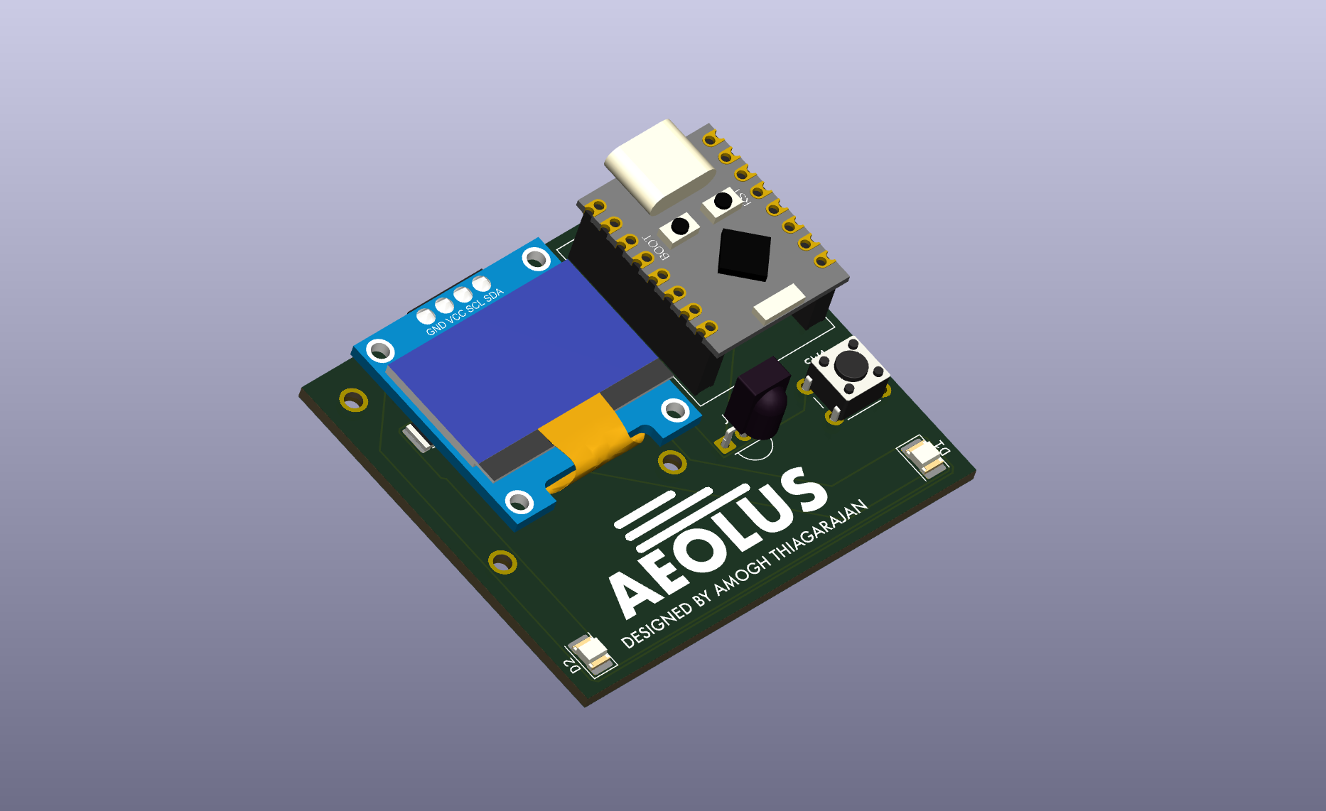
3D render
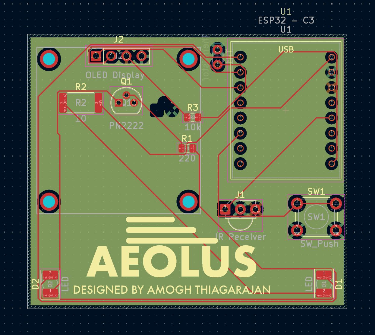
PCB layout (4-layer, black soldermask, silkscreen branding)
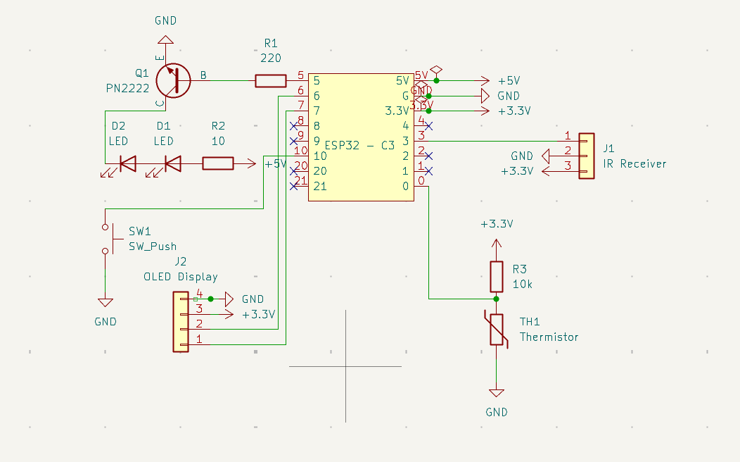
Schematic
Aeolus is a ground-up redesign of my earlier dorm-room fan automation project. The original ("fans") was an Arduino Uno R3 on a breadboard: a DHT11 sensor, an IR receiver, and a transistor-driven IR LED that automatically toggled the fan on hysteresis. It worked, but it was bulky, code-only, and limited to hardcoded remote codes.
Aeolus keeps the proven control logic and rebuilds everything around it as a real, compact, hardware product.
fans)| Area | v1 — fans | v2 — Aeolus |
|---|---|---|
| Microcontroller | Arduino Uno R3 (ATmega328P, 5V, large) | ESP32-C3 SuperMini (32-bit RISC-V, 3.3V, tiny, Wi-Fi/BLE capable) |
| Temperature sensing | DHT11 module (slow, ~1 Hz, NaN dropouts) | NTC thermistor read on the ADC with a Beta-equation conversion — faster, cheaper, no library timing quirks |
| Display | None (serial monitor only) | 0.96" SSD1306 I²C OLED with live temp/state readout and wind/snow animations |
| User input | None | Physical push button — single/double-tap for mode and manual control |
| Remote codes | Hardcoded in firmware | On-device IR learn/scan mode — capture a new remote's code without reflashing |
| Build | Breadboard / protoboard prototype | Custom 4-layer PCB designed in KiCad (SIG–GND–PWR–SIG stackup), black soldermask, silkscreen branding |
| Form factor | Loose modules and jumper wires | Single integrated board with the OLED and modules socketed |
The transistor-buffered IR transmitter (the key range fix from v1 — extends usable range from a couple of inches to ~10–15 ft) is carried over into the Aeolus hardware.
0x3C)hardware/Aeolus.kicad_pcb / .kicad_sch)| Function | ESP32-C3 GPIO |
|---|---|
| IR transmit | GPIO5 |
| IR receive | GPIO3 |
| OLED SDA | GPIO7 |
| OLED SCL | GPIO6 |
| Button | GPIO10 |
| Thermistor (ADC) | GPIO0 |
The firmware lives in src/main.cpp and is built with PlatformIO (Arduino framework for ESP32-C3).
This is a PlatformIO project:
pio run              # build
pio run -t upload    # flash to the ESP32-C3
pio device monitor   # serial output
Board and framework are configured in platformio.ini. Libraries used: IRremote, Adafruit SSD1306, Adafruit GFX.
The KiCad 9 project is in hardware/ (schematic, PCB, custom symbol/footprint libraries). Highlights:
In1.Cu carries a poured GND plane and In2.Cu a poured +3.3V plane. Every ground and supply pad is through-hole, so the plated barrels tie straight into the planes with thermal reliefs and no stitching vias are needed. That is why there is not a single GND trace on F.Cu — the plane carries every return, which keeps the loop area of the switched IR LED current away from the high-impedance thermistor sense line.branding/.hardware/Aeolus.3dshapes/ for a complete 3D render.Stated up front so the files and the description agree:
F.Cu; B.Cu is unused for routing. This is fine at this node count because power and ground are handled by the inner planes rather than by surface traces.schematic-guide.txt calls for 100 nF on the OLED and IR receiver supplies; those parts are not yet in the schematic.hardware/ is layout and 3D render only; no gerbers, BOM, or assembled unit yet.See LICENSE.
| Qty | Value | Footprint | References |
|---|---|---|---|
| 2 | LED | LED_SMD:LED_PLCC-2_3.4x3.0mm_KA | D1, D2 |
| 1 | 10 | Resistor_SMD:R_2512_6332Metric | R2 |
| 1 | 10k | Resistor_SMD:R_0805_2012Metric | R3 |
| 1 | 220 | Resistor_SMD:R_0805_2012Metric | R1 |
| 1 | ESP32 - C3 | Aeolus_footprints:ESP32-C3-SuperMini | U1 |
| 1 | IR Receiver | OptoDevice:Vishay_MINICAST-3Pin | J1 |
| 1 | OLED Display | Aeolus_footprints:OLED_SSD1306_I2C_0.96 | J2 |
| 1 | PN2222 | Package_TO_SOT_THT:TO-92 | Q1 |
| 1 | SW_Push | Button_Switch_THT:SW_PUSH_6mm | SW1 |
| 1 | Thermistor | Capacitor_THT:C_Disc_D3.0mm_W1.6mm_P2.50mm | TH1 |
The 11 most common of 12 parts.
It measures 53.3 × 45.7 mm and has 4 copper layers, 1.6 mm thick.
12 parts, built around the PN2222A. The full list of its parts is on this page, with links to each part's symbol and footprint where PCBKit's library has them.
From the am0ghh/Aeolus repository on GitHub, at the commit this page was made from: the board is hardware/Aeolus.kicad_pcb and its schematic hardware/Aeolus.kicad_sch. PCBKit opens the board in the browser, with nothing to install.
Its repository publishes it under the MIT licence: you may reuse it on that licence's terms (keep the author's notice, and for a copyleft licence share your changes alike).
skiselev/micro_8088
Micro 8088 - IBM XT Compatible Processor Board based on Faraday FE2010 chipset

Staacks/there.oughta.be
Projects featured on my blog at https://there.oughta.be


plusvic/simplebus2-intercom
General description of the Simplebus2 protocol used by some Comelit's intercoms. Hardware for retransmitting Simplebus2 messages over UART.


