2 layers357.8 × 124.5 mm
Vic2020mainboard
danwerner21/vic2020
A Vic-20 clone created with [almost] all readily available parts
142 parts78

 alvaroalea/QL_Minerva_MK26
Clone of the Board of ROM + RTC for Sinclair QL Computer
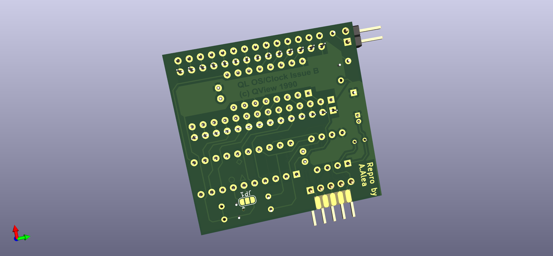
QL Minerva MK2 is an open-source printed circuit board by alvaroalea, from the alvaroalea/QL_Minerva_MK2 repository on GitHub. It is a 2-layer board of 40.6 × 44.5 mm with 16 parts on 42 nets, routed with 278 tracks and 2 vias.
It is built around the 74LS133PC, W27C512-45Z and BAT42. Its parts include 5 ICs, 3 capacitors, 3 resistors, 2 connectors and 1 diode. It belongs with the FPGA and CPLD and NXP (LPC, Kinetis, i.MX RT) boards of this library.


In 2024 by Alvaro Alea Fernandez
License under: CERN Open Hardware Licence Version 2 - Strongly Reciprocal
https://ohwr.org/cern_ohl_s_v2.txt
My work is only copy the design to Kicad, all (C) are retaing to the original owners.
U1 shall be pin row, to be mounted in the solder side, in a way that allow to insert on the Sinclair QL's Rom socket.
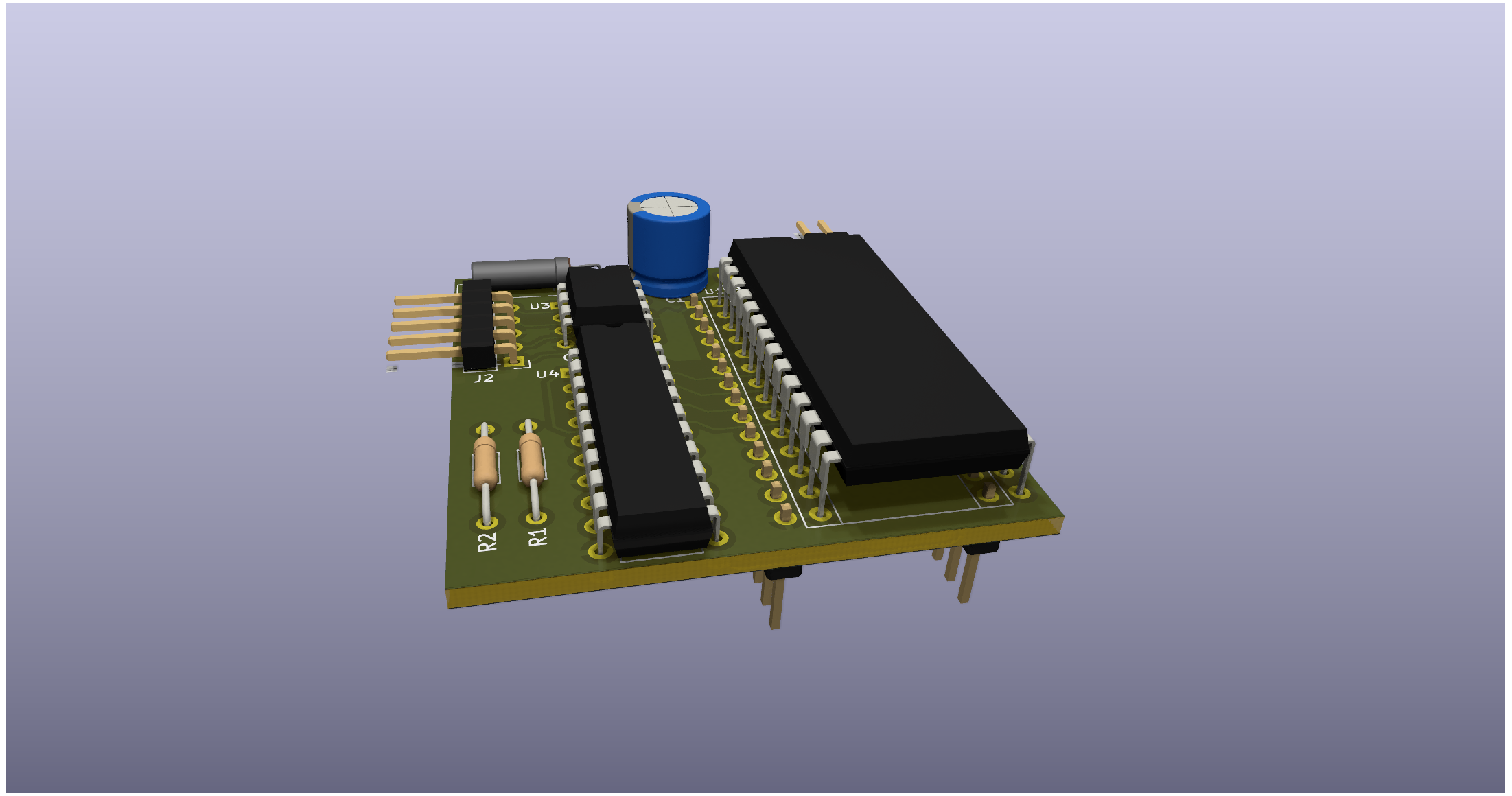
U5 shall be solder without socket under U2.
U2 shall be solder with a socket to allow space for U5.
Original Information of minerva can be found here: http://tfs.firshman.co.uk/ql/minerva.htm
A generic description here: https://wiki.qlforum.co.uk/doku.php?id=qlwiki:minerva
Manuals and software here: https://dilwyn.qlforum.co.uk/docs/manuals/index.html
Main information, GAL code, pictures, etc... has been obtained from this post: https://qlforum.co.uk/viewtopic.php?t=1993
ROM Chip shall be installed as per this picture:
| Qty | Value | Footprint | References |
|---|---|---|---|
| 2 | 2K2 | 8bits:R_Axial_DIN0204_L3.6mm_D1.6mm_P11.17mm_Horizontal | R1, R2 |
| 2 | C | Capacitor_THT:C_Disc_D3.0mm_W1.6mm_P2.50mm | C2, C3 |
| 1 | 120 | 8bits:R_Axial_DIN0204_L3.6mm_D1.6mm_P11.17mm_Horizontal | R3 |
| 1 | 30p Variable | 8bits:C_Variable_Radial_D6.0mm_P5.00mm | C1 |
| 1 | 32.768 kHz | Crystal:Crystal_AT310_D3.0mm_L10.0mm_Horizontal | Y1 |
| 1 | 74LS133 | Package_DIP:DIP-16_W7.62mm | U5 |
| 1 | BAT42 | Diode_THT:D_DO-35_SOD27_P7.62mm_Horizontal | D1 |
| 1 | Conn_01x02_Pin | Connector_PinHeader_2.54mm:PinHeader_1x02_P2.54mm_Horizontal | J1 |
| 1 | Conn_01x05_Pin | Connector_PinHeader_2.54mm:PinHeader_1x05_P2.54mm_Horizontal | J2 |
| 1 | GAL16V8 | Package_DIP:DIP-20_W7.62mm | U4 |
| 1 | PCF8583P | Package_DIP:DIP-8_W7.62mm | U3 |
| 1 | Socket to QL | Package_DIP:DIP-28_W15.24mm | U1 |
| 1 | SolderJumper_3_Open | Jumper:SolderJumper-3_P1.3mm_Bridged12_RoundedPad1.0x1.5mm | JP1 |
| 1 | W27C512 | Package_DIP:DIP-28_W15.24mm | U2 |
danwerner21/vic2020
A Vic-20 clone created with [almost] all readily available parts

jbevren/6809v2
Code and design repository for the 6809v2 SBC: To be released at VCFMW 13


jimbro1000/Commodore-Vic-20
Late, cost reduced vic-20 schematic and board

RichCini/VIC-20-Reloaded
Reimaging of the original VIC-20cr ("cost-reduced") main board in a smaller footprint.


eduardocasino/kim-1-mtu-ram-rom
KIM-1 RAM/ROM Expansion Board for the MTU Backplane
It measures 40.6 × 44.5 mm and has 2 copper layers, 1.6 mm thick.
16 parts, built around the 74LS133PC, W27C512-45Z and BAT42. The full list of its parts is on this page, with links to each part's symbol and footprint where PCBKit's library has them.
From the alvaroalea/QL_Minerva_MK2 repository on GitHub, at the commit this page was made from: the board is QL_Minerva_MK2.kicad_pcb and its schematic QL_Minerva_MK2.kicad_sch. PCBKit opens the board in the browser, with nothing to install.
Its repository states no licence, so its author keeps all rights: ask alvaroalea before reusing the design.