2 layers

 alpyen/zynq-gbcartreader3
Embedded Software Development project to read & write GameBoy cartridges.
Pmod interface board is an open-source printed circuit board by alpyen, from the alpyen/zynq-gbcartreader repository on GitHub. It is a 4-layer board of 81.7 × 61 mm with 31 parts on 65 nets, routed with 325 tracks and 57 vias.
It is built around the 74HCT541D, 74HC595 and 74HC597D. Its parts include 15 resistors, 6 capacitors, 6 ICs and 4 connectors. It belongs with the retro computing and games and fPGA and programmable logic boards and the FPGA and CPLD boards of this library.


This project is aimed to dive into FPGA SoCs and embedded software development by designing a system that's able to read and write to gameboy cartridges with a custom designed PCB which interfaces between the FPGA and the game cartridge.
Starting from a very basic bitbanging implementation solely running on the ARM core, the following design iterations will make use of a more sophisticated architecture by offloading the board communication to an IP core and moving commands and responses around with AXI interfaces.
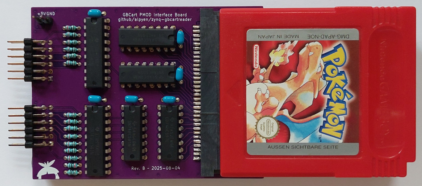
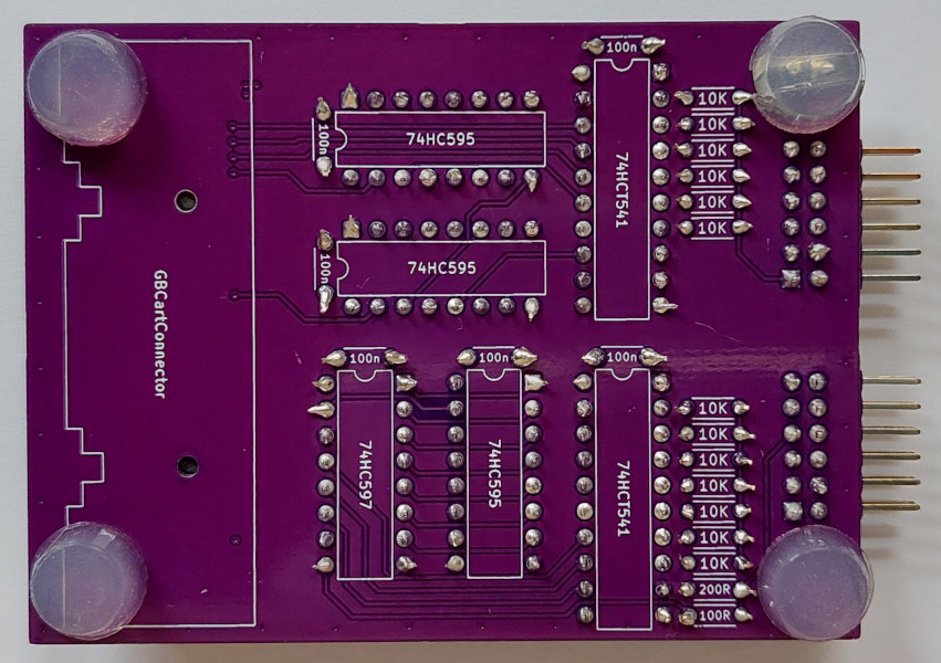
There are a couple of different cartridge types that mostly distinguish between the type of mapper chip and additional periphery such as RAM, Real-Time-Clock, Battery and more. Here's a list of the ones that are available:
| Type | Status | Verified On |
|---|---|---|
| No MBC | ✅ | Motocross Maniacs (DMG-MX-NOE) Othello (DMG-OT-NOE) |
| MBC1 | ✅ | ポケットモンスター 緑 (DMG-APBJ-JPN) Super Mario Land (DMG-ML-NOE) |
| MBC2 | ✅ | F-1 RACE (DMG-F1-NOE) |
| MBC3 | ✅ | Pokémon Crystal (CGB-BYTD-NOE) Pokémon Silver (DMG-AAXD-NOE) |
| MBC5 | ✅ | Pokémon Red (DMG-APAD-NOE) Pokémon Blue (DMG-APED-NOE) Pokémon Yellow (DMG-APSD-NOE) |
| MBC30 | ✅ | ポケットモンスター クリスタルバージョン (CGB-BXTJ-JPN) |
Some exotic cartridges exist which are not supported. For an exhaustive list check the Pan Docs and GameBoy hardware database. Most games simply use No MBC, MBC1, 3 or 5. If I own any of the uncommon ones I'll implement them, otherwise I'll skip them as I cannot verify them.
This project supports reading the ROM, reading and writing to RAM allowing you to dump games, backup save files and also restore save files back to the cartridge. Reading and Writing RTC data is not supported.
I've noted that some games can underreport the number of ROM or RAM banks, for example ポケットモンスター 緑 or ポケットモンスター クリスタルバージョン. They only report half as many banks present, but manually fixing them in the software dumps these correctly too.
This step assumes you have your FPGA-board configured with the application up and running.
Interfacing with the FPGA-board is done through python scripts by sending data over a serial port. Please refer to Setting up the virutal environment on how to create a virtual environment and install the pip packages (pyserial) to use the scripts.
The board communicates with a baudrate of 115200 and is plugged in to /dev/ttyUSB1 on my machine.
Check if your setup is healthy by runing the help command:
(.venv) zynq-gbcartreader/python$ python reader.py -b 115200 -p /dev/ttyUSB1 help
Sending command: help
Receiving data...482B/482B...done!
ZYNQ GBCartReader - Read & Write Gameboy cartridges
written by alpyen - visit the project on github.com/alpyen/zynq-gbcartreader

Available commands:
-------------------
help          Display this help page
parse header  Read cartridge header and parse into readable form
read rom      Read cartridge rom and echo it in binary
read ram      Read cartridge ram (if available) and echo it in binary
write ram     Write cartridge ram (if available) from binary terminal data
A help screen should be printed which is sent by the applicaton running on the FPGA-board. If you do not receive any text or the connection hangs, make sure to correctly flash the board, and check your access permissions on that serial port.
Plugging in a Pokémon Crystal cartridge (CGB-BYTD-NOE) I can read out its header:
(.venv) zynq-gbcartreader/python$ python reader.py -b 115200 -p /dev/ttyUSB1 parse header
Sending command: parse header
Receiving data...858B/858B...done!
Overview:
  Entry Point:       00 C3 6E 01
  Nintendo Logo:     Good
  Title:             PM_CRYSTAL
  Manufac. Code (?): BYTD
  CGB Flag:          CGB exclusive
  New Licensee Code: Nintendo Research & Development 1
  SGB Flag:          No
  Type:              MBC3 + RTC + RAM + Battery
  ROM Size:          2048 KiB (128 banks)
  RAM Size:          32 KiB (4 banks)
  Destination Code:  Overseas
  Old Licensee Code: Check New Licensee Code
  Version:           00
  Header Checksum:   28 (Good)
  Global Checksum:   49 82

Full Header:
  0x0100:  00 C3 6E 01 CE ED 66 66 CC 0D 00 0B 03 73 00 83
  0x0110:  00 0C 00 0D 00 08 11 1F 88 89 00 0E DC CC 6E E6
  0x0120:  DD DD D9 99 BB BB 67 63 6E 0E EC CC DD DC 99 9F
  0x0130:  BB B9 33 3E 50 4D 5F 43 52 59 53 54 41 4C 00 42
  0x0140:  59 54 44 C0 30 31 00 10 06 03 01 33 00 28 49 82
Now all you have do to dump this cartridge is to use the read rom function. The python script will
output the contents onto stdout while printing the current progress onto stderr. Pipe the result
into a file like so:
(.venv) zynq-gbcartreader/python$ python reader.py -b 115200 -p /dev/ttyUSB1 read rom > cartridge.gb
Sending command: read rom
Receiving data...2048K/2048K...done!
The file extension does not really matter, it is recommended to simply use one that downstream tools like emulators or inspection tools can handle.
Dumping the cartridge RAM is as straightforward, simply replace read rom with read ram.
Use write ram and either pipe in the RAM file or redirect stdin like so:
(.venv) zynq-gbcartreader/python$ python reader.py -b 115200 -p /dev/ttyUSB1 write ram < cartridge.sav
Sending command: write ram
Sending size...done!
Sending data...32K/32K...done!
Note: Since RTC reads/writes are not implemented some games may ask you to re-set the clock.
This project was developed with Vivado/Vitis 2025.1 and uses scripts for these versions. It should be possible to recreate the projects with minimal hassle on different versions.
Currently the PYNQ-Z2 with the software running on the ARM and the Basys3 with the software running on a MicroBlaze-V soft core processor are supported.
Note: This step can be skipped if a pre-built XSA is downloaded from the releases section. Place it in the vivado subfolder and continue with the Vitis section.
You can regenerate the project by starting Vivado and opening the tcl console.
Navigate with cd into the vivado subfolder and either run
source regenerate_pynq_z2.tcl or source regenerate_basys3.tcl.
Vivado will rebuild the project from the source files. Once that's done you can generate the wrappers for the different block design implementations, synthesize and export the XSA files for use in Vitis.
Note: The automatic wrapper generation is not implemented for now.
Vitis offers a python interface to dispatch commands from scripts to the application. In order to use this, you need to source the settings64.sh from the Vitis installation. If you've installed the Xilinx tools in the default location then open up a new terminal and load the settings by running these commands based on your operating system:
call C:/Xilinx/2025.1/Vitis/settings64.batsource /opt/Xilinx/2025.1/Vitis/settings64.shIn the same terminal navigate with cd into the vitis subfolder and either run
vitis -s regenerate.py pynq-z2 or vitis -s regenerate.py basys3.
Note: This script has to be run from Vitis, it will not work with your local python installation.
Unfortunetaly only later versions of Vitis support compilation settings through the Python API so some entries have to be manually configured for the Basys3 build which the script will warn you about when creating the Vitis project.
The script takes care of several things:
Once the regeneration is complete you can open the Vitis GUI and set the workspace to the vitis subfolder. Now you're ready to build the applications and deploy them.
This project heavily relies on the work of others who have reverse engineered and documented the inner workings of the Game Boy and its cartridges and/or compiled existing information:
| Qty | Value | Footprint | References |
|---|---|---|---|
| 13 | 10K | Resistor_THT:R_Axial_DIN0204_L3.6mm_D1.6mm_P5.08mm_Horizontal | R1, R2, R3, R4, R5, R6, R7, R8, R9, R10, R11, R12, R13 |
| 6 | 100nF | Capacitor_THT:C_Disc_D4.7mm_W2.5mm_P5.00mm | C1, C2, C3, C4, C5, C6 |
| 3 | 74HC595 | Package_DIP:DIP-16_W7.62mm | U3, U4, U5 |
| 2 | 74HCT541 | Package_DIP:DIP-20_W7.62mm | U1, U2 |
| 1 | 100R | Resistor_THT:R_Axial_DIN0204_L3.6mm_D1.6mm_P5.08mm_Horizontal | R14 |
| 1 | 200R | Resistor_THT:R_Axial_DIN0204_L3.6mm_D1.6mm_P5.08mm_Horizontal | R15 |
| 1 | 74HC597 | Package_DIP:DIP-16_W7.62mm | U6 |
| 1 | Gameboy Cart Connector | pmod-interface-board:GBCartConnector | J4 |
| 1 | PMOD Connector 1 | Connector_PinHeader_2.54mm:PinHeader_2x06_P2.54mm_Horizontal | J1 |
| 1 | PMOD Connector 2 | Connector_PinHeader_2.54mm:PinHeader_2x06_P2.54mm_Horizontal | J2 |
| 1 | ~ | Connector_PinHeader_2.54mm:PinHeader_1x02_P2.54mm_Vertical | J3 |


Desval27/Gateometry
Gateometry is an Arduino-based, 8-channel Euclidean rhythm generator for Eurorack synthesizers, featuring programmable rhythms, individual gate outputs and mute switches, external clock synchronization, and an OLED…


papaya/MB_ModulBox_NG
MBModulBoxNG est une bibliothèque de cartes de contrôle physiques pour le système MIDIbox NG. Les sources, schémas, PCB et fichiers de fabrication ne sont pas tous disponibles pour chaque carte.

Smoothieware/Smoothieboard2
Hardware files for the Smoothieboard v2, and extension boards
It measures 81.7 × 61 mm and has 4 copper layers, 1.6 mm thick.
31 parts, built around the 74HCT541D, 74HC595 and 74HC597D. The full list of its parts is on this page, with links to each part's symbol and footprint where PCBKit's library has them.
From the alpyen/zynq-gbcartreader repository on GitHub, at the commit this page was made from: the board is kicad/pmod-interface-board.kicad_pcb and its schematic kicad/pmod-interface-board.kicad_sch. PCBKit opens the board in the browser, with nothing to install.
Its repository states no licence, so its author keeps all rights: ask alpyen before reusing the design.