

2 layers76.5 × 38.1 mm

 alphaseneca/4-4-4_led_cube
An interactive 4x4x4 LED Cube project with PCB design, code, debugging logs, and lessons learned, documenting my journey and future improvements.
444 led cube pcb is an open-source printed circuit board by alphaseneca, from the alphaseneca/4-4-4_led_cube repository on GitHub. It is a 2-layer board of 99 × 99 mm with 49 parts on 34 nets, routed with 124 tracks and 0 vias.
It is built around the WEMOS D1 MINI and 74HC595. Its parts include 4 inductors, 3 ICs and 1 connector. It belongs with the ESP8266 boards of this library.
This repository documents my journey of building a 4x4x4 LED Cube, including the code, PCB designs, mistakes I made, lessons learned and resources I found along the way. The goal is to use this repository as a learning journal and a reference for others. This project continues to evolve as I improve the design and explore new features.
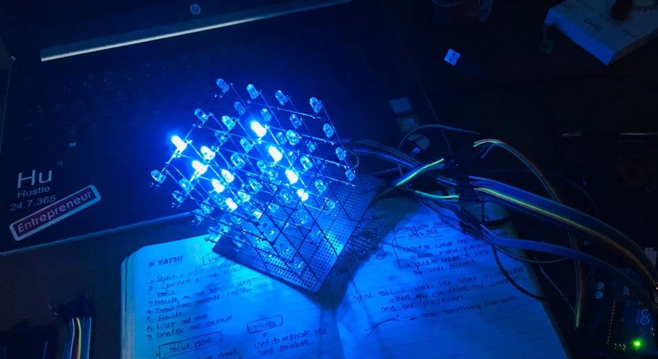
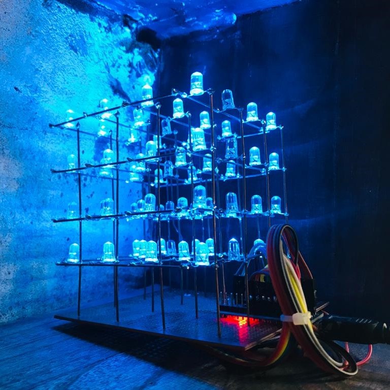
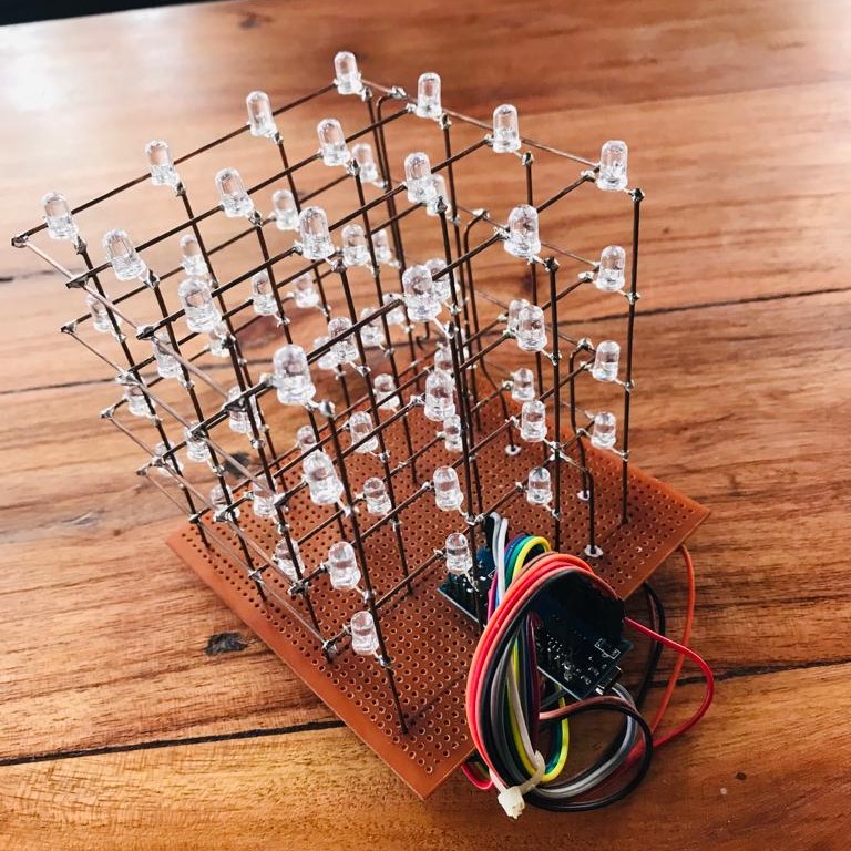
The 4x4x4 LED Cube consists of 64 LEDs arranged in a 3D matrix, controlled using a microcontroller (Arduino in this case). The goal was to create various light patterns by programming the cube and experimenting with animations.
images/: Photos of the build progress and final results.4-4-4_led_cube_code/: Contains the code for programming the LED cube.4-4-4_led_cube_pcb/: Documentation for all PCB versions.
v1.0/: First version of the PCB, including Gerber files and 3D renderings.v2.0/: Placeholder for future PCB improvements.changelog.md: Summarizes changes across PCB iterations.debugging/: Notes on issues encountered and how I solved them.4-4-4_led_cube_code/ folder.main.cpp file in the location 4-4-4_led_cube_code/src/ and build it.After seeing a lot of videos on led cube and having the interest to make the room a bit colourful with my own creations, I decided to build a 4x4x4 LED Cube.
Firstly, I gathered the materials and then startred working on the cube itself. The first thing I did was made a frame that could hold the led array so that they will be in the same location. Then started soldering the leds after bending their leads. The next step was to add the array to the frame. And after that the cube was done and after the wiring the 4x4x4 cube was ready.
Creating the PCB for this project was an experience in itself. After completing the cube design, I started working on the PCB. I started with the first version of the PCB with the same design as the original prototype design just to make the wiring more neat and the cube more useable.
This is just the beginning! I plan to continue refining the design, adding new features, and maybe even explore wireless control to unlock more creative possibilities.
Issue 1: The Arduino Nano did not accepted the code.
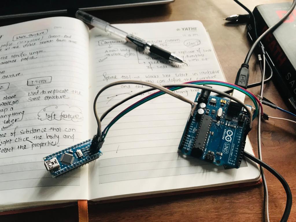
Old Bootloader.Issue 2: The light was strobing a lot.
| Qty | Value | Footprint | References |
|---|---|---|---|
| 4 | MountingHole_Pad | MountingHole:MountingHole_3mm_Pad_TopBottom | H21, H22, H23, H24 |
| 2 | 74HC595 | Package_DIP:DIP-16_W7.62mm | U2, U3 |
| 1 | A1 | wirebase:wirebase_footprint | H1 |
| 1 | A2 | wirebase:wirebase_footprint | H2 |
| 1 | A3 | wirebase:wirebase_footprint | H3 |
| 1 | A4 | wirebase:wirebase_footprint | H4 |
| 1 | B1 | wirebase:wirebase_footprint | H5 |
| 1 | B2 | wirebase:wirebase_footprint | H6 |
| 1 | B3 | wirebase:wirebase_footprint | H7 |
| 1 | B4 | wirebase:wirebase_footprint | H8 |
| 1 | Barrel_Jack | Connector_BarrelJack:BarrelJack_Horizontal | J1 |
| 1 | C1 | wirebase:wirebase_footprint | H9 |
| 1 | C2 | wirebase:wirebase_footprint | H10 |
| 1 | C3 | wirebase:wirebase_footprint | H11 |
| 1 | C4 | wirebase:wirebase_footprint | H12 |
| 1 | D1 | wirebase:wirebase_footprint | H13 |
| 1 | D2 | wirebase:wirebase_footprint | H14 |
| 1 | D3 | wirebase:wirebase_footprint | H15 |
| 1 | D4 | wirebase:wirebase_footprint | H16 |
| 1 | G*** | kibuzzard-6643DB1C | kibuzzard-6643DB1C |
| 1 | G*** | kibuzzard-6643D9FF | kibuzzard-6643D9FF |
| 1 | G*** | kibuzzard-6643D9ED | kibuzzard-6643D9ED |
| 1 | G*** | kibuzzard-6643DA1F | kibuzzard-6643DA1F |
| 1 | G*** | kibuzzard-6643DBED | kibuzzard-6643DBED |
| 1 | G*** | kibuzzard-6643DBE7 | kibuzzard-6643DBE7 |
| 1 | G*** | kibuzzard-6643DBBB | kibuzzard-6643DBBB |
| 1 | G*** | kibuzzard-6643DBE0 | kibuzzard-6643DBE0 |
| 1 | G*** | kibuzzard-6643DB44 | kibuzzard-6643DB44 |
| 1 | G*** | kibuzzard-6643DBDA | kibuzzard-6643DBDA |
| 1 | G*** | kibuzzard-6643DB5E | kibuzzard-6643DB5E |
| 1 | G*** | kibuzzard-6643DB4E | kibuzzard-6643DB4E |
| 1 | G*** | kibuzzard-6643DAE2 | kibuzzard-6643DAE2 |
| 1 | G*** | kibuzzard-6643DBC3 | kibuzzard-6643DBC3 |
| 1 | G*** | kibuzzard-6643DB07 | kibuzzard-6643DB07 |
| 1 | G*** | kibuzzard-6643DBCA | kibuzzard-6643DBCA |
| 1 | G*** | kibuzzard-6643DA2D | kibuzzard-6643DA2D |
| 1 | G*** | kibuzzard-6643DBF5 | kibuzzard-6643DBF5 |
| 1 | G*** | kibuzzard-6643DBD4 | kibuzzard-6643DBD4 |
| 1 | G*** | kibuzzard-6643DAD8 | kibuzzard-6643DAD8 |
| 1 | LOGO | wirebase:logo | G*** |
| 1 | Layer1 | wirebase:wirebase_footprint | L1 |
| 1 | Layer2 | wirebase:wirebase_footprint | L2 |
| 1 | Layer3 | wirebase:wirebase_footprint | L3 |
| 1 | Layer4 | wirebase:wirebase_footprint | L4 |
| 1 | WeMos_D1_mini | Module:WEMOS_D1_mini_light | U1 |


nkitanov/iaq_board
IAQ Board is a DIY (Do-It-Yourself) device for measuring internal air quality

bitfixer/bf-romulator
Romulator - RAM/ROM replacement and debug for 6502 CPU systems

alcar21/WemosEM
Cheap power monitor (STC013) with Home Assistant Discover and Wemos D1 Mini / PRO (esp8266)

It measures 99 × 99 mm and has 2 copper layers, 1.6 mm thick.
49 parts, built around the WEMOS D1 MINI and 74HC595. The full list of its parts is on this page, with links to each part's symbol and footprint where PCBKit's library has them.
From the alphaseneca/4-4-4_led_cube repository on GitHub, at the commit this page was made from: the board is 4-4-4_led_cube_pcb/v1.0/444_led_cube_pcb.kicad_pcb and its schematic 4-4-4_led_cube_pcb/v1.0/444_led_cube_pcb.kicad_sch. PCBKit opens the board in the browser, with nothing to install.
Its repository states no licence, so its author keeps all rights: ask alphaseneca before reusing the design.