

2 layers70.1 × 43.2 mm
Iaq device
nkitanov/iaq_board
IAQ Board is a DIY (Do-It-Yourself) device for measuring internal air quality
19 parts396

 alphaseneca/fibonacci_clock
A unique clock that uses the Fibonacci sequence to display time with colored squares, combining math and art in an innovative timekeeping design.
Fibonacci clock pcb is an open-source printed circuit board by alphaseneca, from the alphaseneca/fibonacci_clock repository on GitHub. It is a 2-layer board of 105 × 90 mm with 13 parts on 52 nets, routed with 314 tracks and 7 vias.
It is built around the WEMOS D1 MINI. Its parts include 5 ICs and 3 connectors. It belongs with the lEDs and displays boards and the ESP8266 boards of this library.
A unique clock project that combines math and electronics using the Fibonacci sequence to display time with colored segments. Powered by a Wemos D1 Mini, it fetches the current time using NTP. This repository serves as a learning journal, tracking the development process, inspirations, troubleshooting, and future improvements.
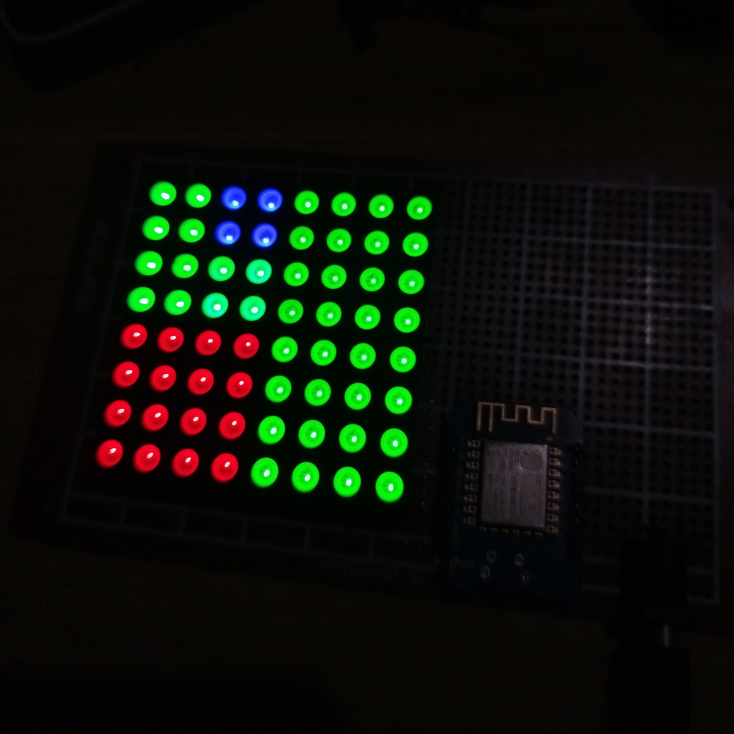
images/: Photos of the clock and its working principle.fibonacci_clock_code/: Contains the code to run the Fibonacci clock logic.fibonacci_clock_pcb/: Files and documentation for the PCB design.debugging/: Logs of issues encountered and solutions applied during development.The Fibonacci Clock displays time by lighting up segments of a matrix corresponding to Fibonacci numbers.
Working Principle Diagram:
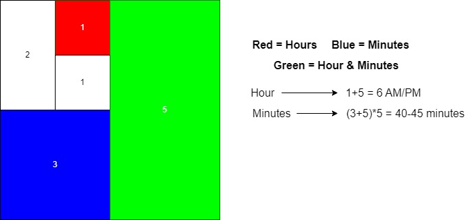
Segments only represent numbers between 1 - 12, and minute values are scaled by multiplying by 5.
Time increments are in 5-minute intervals, so valid minute values range between 40 - 45 minutes.
Building this clock has been an exciting adventure. It started as a simple idea to make a desktop artpiece that is bit unique and looks cool and ended up being a timekeeping device. Using the Wemos D1 Mini to sync time with NTP added complexity but opened new possibilities.
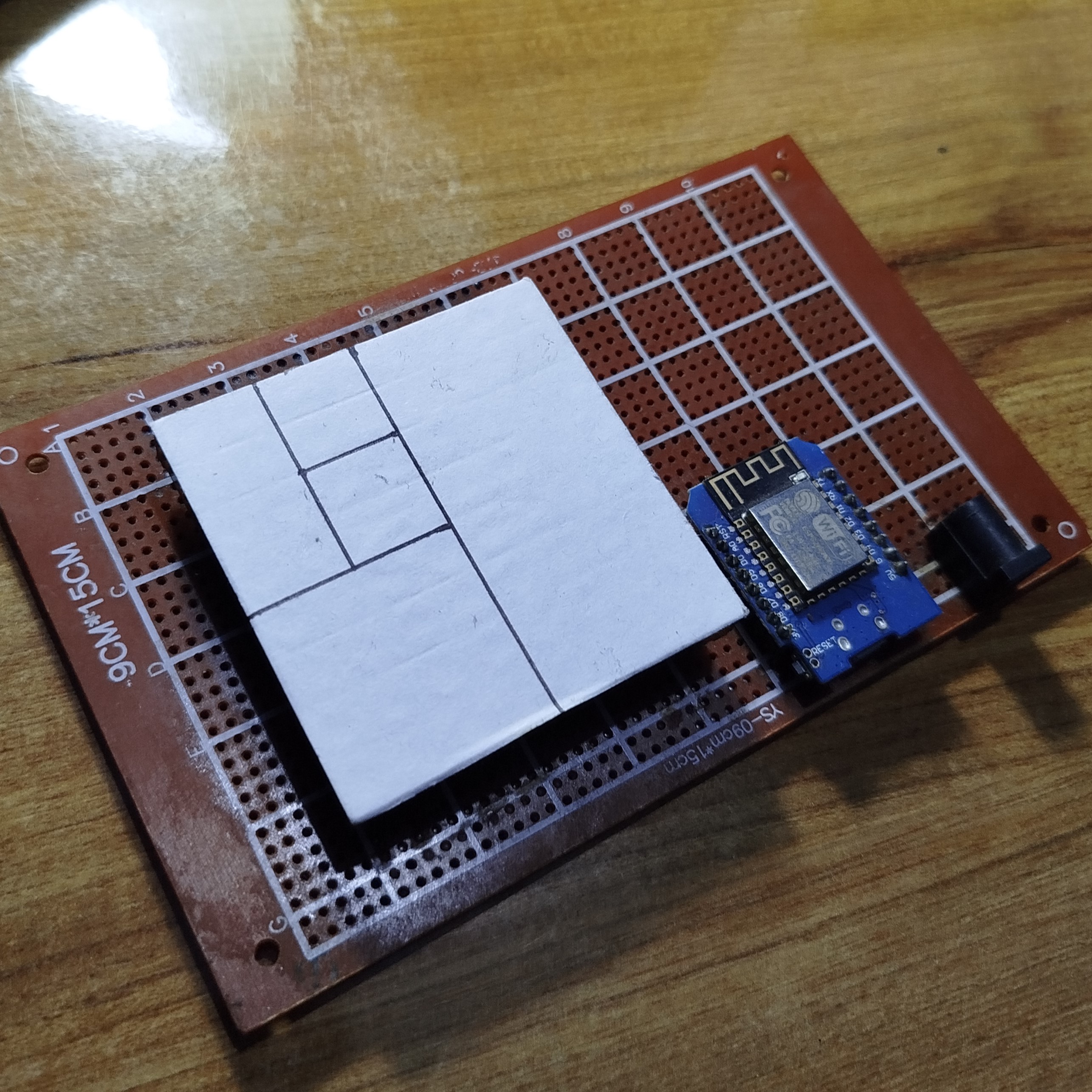
Creating the PCB design was also a journey in its own. I started with the prefboard and the main project is still on the prefboard but for the further development and to make the device look clean and more presentable the PCB design was created.
The pcb that I created is not complete. It is still a work in progress and nowhere near to the original design. I am planning to make the project like the main original design itself.
Future iterations may include offline timekeeping by integrating an RTC module to eliminate reliance on NTP. Wireless control and animations are also on the horizon!
Just a current solution though. Planning to remove the second solution in the future busing MAX7219 chip rather than the LM74HC595 chip.
This repository will continue to evolve as I experiment with new features and improvements.
| Qty | Value | Footprint | References |
|---|---|---|---|
| 4 | MountingHole_Pad | MountingHole:MountingHole_3mm_Pad_TopBottom | H1, H2, H3, H4 |
| 1 | Blue | Package_DIP:DIP-16_W7.62mm | U4 |
| 1 | Bottom 16 | Connector_PinSocket_2.54mm:PinSocket_1x16_P2.54mm_Vertical | J2 |
| 1 | Cathode | Package_DIP:DIP-16_W7.62mm | U1 |
| 1 | Green | Package_DIP:DIP-16_W7.62mm | U3 |
| 1 | Jack-DC | Connector_BarrelJack:BarrelJack_Horizontal | J3 |
| 1 | LOGO | Assets:logo | G*** |
| 1 | Red | Package_DIP:DIP-16_W7.62mm | U2 |
| 1 | Top 16 | Connector_PinSocket_2.54mm:PinSocket_1x16_P2.54mm_Vertical | J1 |
| 1 | WeMos_D1_mini | Module:WEMOS_D1_mini_light | U5 |
It measures 105 × 90 mm and has 2 copper layers, 1.6 mm thick.
13 parts, built around the WEMOS D1 MINI. The full list of its parts is on this page, with links to each part's symbol and footprint where PCBKit's library has them.
From the alphaseneca/fibonacci_clock repository on GitHub, at the commit this page was made from: the board is fibonacci_clock_pcb/fibonacci_clock_pcb.kicad_pcb and its schematic fibonacci_clock_pcb/fibonacci_clock_pcb.kicad_sch. PCBKit opens the board in the browser, with nothing to install.
Its repository states no licence, so its author keeps all rights: ask alphaseneca before reusing the design.
nkitanov/iaq_board
IAQ Board is a DIY (Do-It-Yourself) device for measuring internal air quality

bitfixer/bf-romulator
Romulator - RAM/ROM replacement and debug for 6502 CPU systems

alcar21/WemosEM
Cheap power monitor (STC013) with Home Assistant Discover and Wemos D1 Mini / PRO (esp8266)


kholia/Easy-Digital-Beacons-v1
A simple and easy Arduino / Pi Pico / ESP8266-powered WSPR, FT8, and FT4 beacon system which uses NTP + DS3231 RTC for timing. Super extensible! Now comes with optional GPS support.

htumanyan/navien
Navien water heater wire protocol for communication with NaviLink and other attached devices

