
2 layers58.7 × 17.7 mm
Fpga 5v pin adapter
bitfixer/bf-romulator
Romulator - RAM/ROM replacement and debug for 6502 CPU systems
2 parts160
 bitfixer/bf-romulator160
Romulator - RAM/ROM replacement and debug for 6502 CPU systems
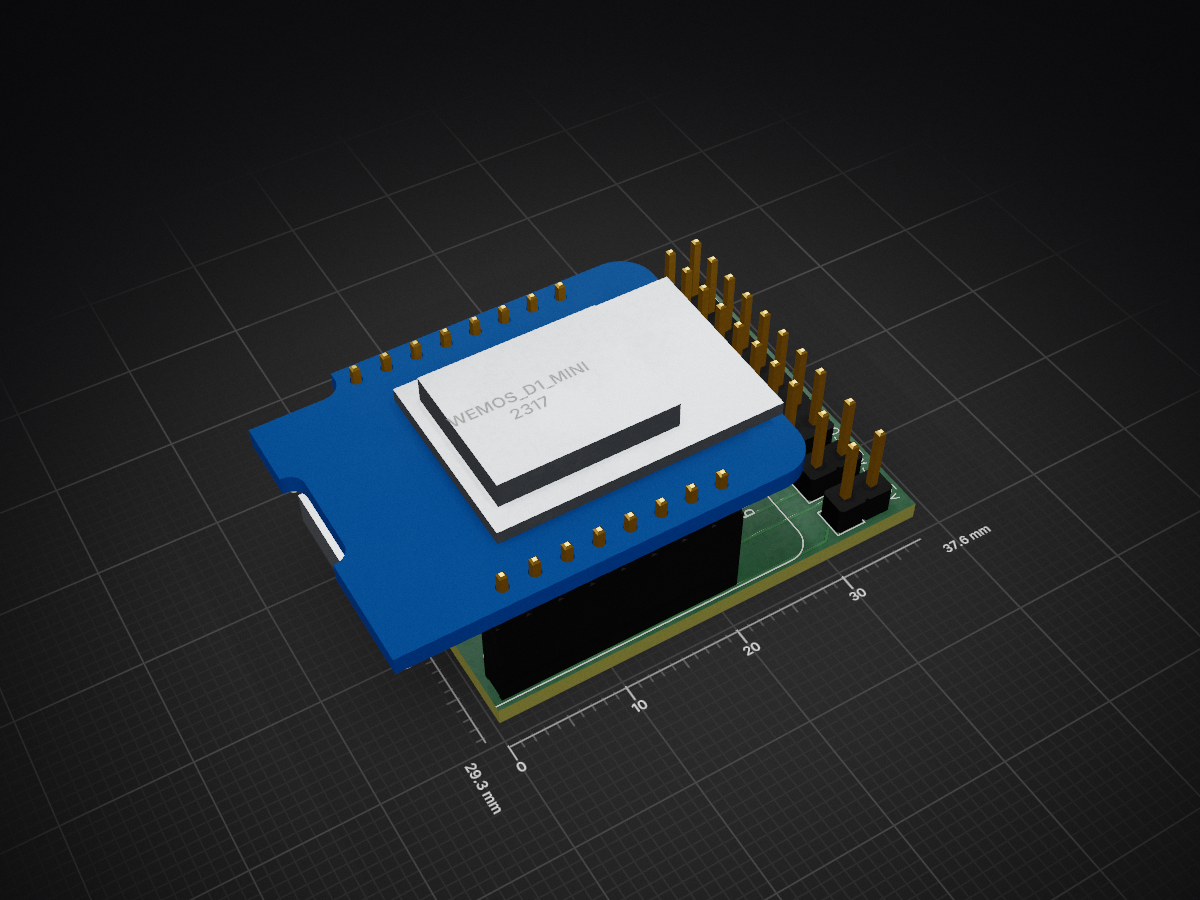
Romulator programmer interface is an open-source printed circuit board by bitfixer, from the bitfixer/bf-romulator repository on GitHub. It is a 2-layer board of 37.6 × 29.3 mm with 5 parts on 25 nets, routed with 91 tracks and 0 vias.
It is built around the WEMOS D1 MINI. Its parts include 4 connectors and 1 IC. It belongs with the interfaces and adapters boards and the ESP8266 boards of this library.
Romulator - RAM/ROM replacement and debug for 6502 and Z80 CPU systems
romulator - verilog code to implement ROMulator RAM/ROM replacement
programmer - programmer and console application for updating ROMulator, and debug
tools - C++ tools for building firmware images for ROMulator
The ROMulator is a RAM/ROM replacement device for 6502 and Z80 systems, with programmable memory maps and debug functionality which allows you to halt a running CPU and read from or write to memory. See https://bitfixer.com/romulator for more information.
This Readme mostly covers the 6502 version for now, more documentation coming soon for Z80.
To use the ROMulator, first remove the 6502 CPU from its socket on the PET (or other computer)'s motherboard. Note the orientation of the notch on the 6502 chip in the socket. Insert the 6502 chip into the 40-pin socket on the ROMulator board. Make sure the notch on the chip is aligned with the notch on the ROMulator socket. Then, take the ROMulator board, and using the pins on the underside of the board, insert it into the 6502 socket on the motherboard. Make sure the notch on the 6502 chip is pointing in its original direction. If the ROMulator is inserted backwards, this may damage the ROMulator board since 5v will be presented where it shouldn't be. Just make sure to double check:
The ROMulator supports up to 32 memory maps. The default memory maps shipped with the ROMulator are currently mostly related to the Commodore PET, but you can add any maps you want via the programming interface. Over time more configurations for common 6502 computers will be added. Please note that these settings reflect the head commit of the repository, and may differ from the default settings on your ROMulator depending on when it was programmed. Building the latest version with make program after a git pull will generate the settings as described.
The default switch settings are as follows:
| Set Index | Setting | Switch 1 | Switch 2 | Switch 3 | Switch 4 |
|---|---|---|---|---|---|
| 0 | BASIC 2, NON-CRTC, Business Kbd (i.e. 2001) | Off | Off | Off | Off |
| 1 | BASIC 4, NON-CRTC (i.e. 2001) | On | Off | Off | Off |
| 2 | BASIC 4, CRTC, 80C (i.e. 8032) | Off | On | Off | Off |
| 3 | BASIC 4, CRTC, 40C (i.e. 4032,4016) | On | On | Off | Off |
| 4 | BASIC 4, PET 4032 60Hz | Off | Off | On | Off |
| 5 | BASIC 2, NON-CRTC, Normal Kbd (i.e. 2001) | On | Off | On | Off |
| 6 | BASIC 4, PET 4032 50Hz | Off | On | On | Off |
| 7 | BASIC 4, PET 4016 60Hz | On | On | On | Off |
| 8 | Apple II plus | Off | Off | Off | On |
| 9 | BASIC 1, PET 2001-8 | On | Off | Off | On |
| 10 | VIC-20 PAL | Off | On | Off | On |
| 11 | VIC-20 NTSC | On | On | Off | On |
| 12 | NOP Generator | Off | Off | On | On |
| 13 | PETTESTER | On | Off | On | On |
| 14 | PET Low RAM Test | Off | On | On | On |
| 15 | PET RAM/ROM/VRAM Test | On | On | On | On |
The memory maps are defined in config/memory_set_default.csv. This file indicates which ROMs are located at which memory address.
This topic is big enough to have its own readme, and it is located here:
config/README.md
Programming and Debugging with the ROMulator can be done in one of two ways:
Information on programming and debugging using the standalone programmer can be found here:
ROMULATOR_STANDALONE.md
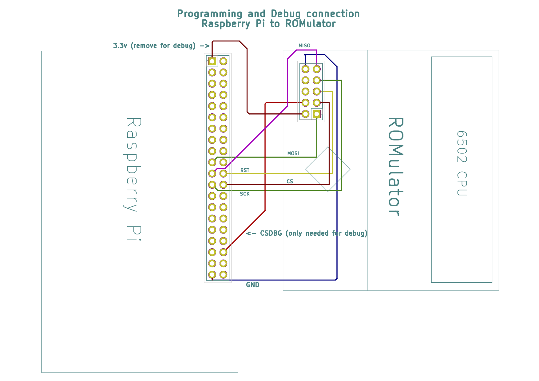
Programming or Debug functionality of the ROMulator uses a Raspberry Pi using a soft SPI implementation. You can use the optional RPI ROMulator programming board, or directly connect the following RPI physical pins to the corresponding pins on the 10-pin header on the ROMulator FPGA board:
| RPI | FPGA Hdr | FPGA Hdr | RPI |
|---|---|---|---|
| 19 | 1 (MOSI) | 2 (3.3v) | 17 |
| 24 | 3 (CS) | 4 (DBG) | 36 |
| 22 | 5 (RST) | 6 (CDONE) | 11 |
| 23 | 7 (SCK) | 8 | NC |
| 21 | 9 (MISO) | 10 (GND) | 34 |
If you are only programming and not running the debug client, DBG and CDONE are optional.
Take a look at this wiring diagram for a visual aid:
The optional RPI ROMulator programming board is just a breakout board for SPI and UART on the Pi which brings SPI0 and SPI1 pins out to separate headers, as well as a UART header. The ROMulator only uses the SPI0 header. If you received a kit for this board, here are a few quick notes on the assembly.
| If your cable looks like this: | Connect it like this. |
 |  |
Or,
| If your cable looks like this: | Connect it like this. |
 |  |
Please follow this procedure to enter debug mode on the romulator and read the contents of a running CPU.
make bin/console from bf-romulator directorymake debug to set appropriate pin directions on the pi. Specifically, this sets the DBG line to 1 to allow the ROMulator to start and not be stuck in a halt state, and sets the RST line to an input to avoid holding the fpga in reset.bin/console -r > output.bin to halt the cpu and read the full memory map into a file called output.bin.To install the ROMulator software on a Raspberry PI for programming or debug, download the script setup.sh onto your Pi and execute from your home directory. This will install the prequisites and fetch the latest version of the code in this repo.
The one-liner for this on the command line is:
wget -O - https://raw.githubusercontent.com/bitfixer/bf-romulator/master/setup.sh | sudo bash
To program a new firmware onto the ROMulator, run
make program
from the ~/bf-romulator directory.
Note that you will need all of the roms present in order to complete the build.
This means that every unique rom specified in config/memory_set_default.csv to be present in the bf-romulator/roms directory.
For convenience if you are downloading ROM images from a single source, there is a script which will do this for you.
If you were downloading every rom with the base url of http://bitfixer.com, you would run the command:
BASEURL=http://bitfixer.com make fetch_roms
This downloads every unique rom specified in config/memory_set_default.csv to the roms directory.
If you just want to program a custom .bin file (if I send you one, for example) the procedure is a bit simpler.
Before the first time doing this run
make bin/programmer_spi
from the ~/bf-romulator directory.
Then, copy the custom .bin file somewhere on your raspberry pi, and run
bin/programmer_spi < customfirmware.bin
from the ~/bf-romulator directory, replacing customfirmware.bin with the actual path of that file.
A recent feature added to the ROMulator is the ability to create a virtual external display, using a connected Raspberry Pi as a webserver. By pointing a browser to the pi server, you will be able to 'see' the contents of video ram in realtime rendered into bitmap images.
Currently, only the PET 2001 is supported, but other 6502 machines with memory-mapped graphics will be added soon.
To use the virtual display feature on a PET 2001, connect the ROMulator to the 6502 socket on the pet, and connect the Pi via the interface board with the programming jumper OFF. For now only setting 1 (Sw 1 ON, rest OFF) is supported, which is BASIC 4.
Power up the PET as usual, and the ROMulator LED should blink on for about one second. Then from the console on your Pi, from the bf-romulator directory, run:
make webserver
Then open a browser on another computer on the same network as the Pi, and navigate to the pi's server, like so:
http://raspberrypi.local:10000/canvas.html
Please note that while the pi will usually show up as raspberrypi.local, this is not always the case and you may need to know the actual local IP. At this point you should be able to enjoy a roughly 15-20 FPS PET 2001 display in your browser!
| Qty | Value | Footprint | References |
|---|---|---|---|
| 3 | Conn_01x02_Male | Connector_PinHeader_2.54mm:PinHeader_1x02_P2.54mm_Vertical | J1, J2, J4 |
| 1 | Conn_02x08_Odd_Even | Connector_PinHeader_2.54mm:PinHeader_2x08_P2.54mm_Vertical | J3 |
| 1 | WeMos_D1_mini | Module:WEMOS_D1_mini_light | U1 |
It measures 37.6 × 29.3 mm and has 2 copper layers, 1.6 mm thick.
5 parts, built around the WEMOS D1 MINI. The full list of its parts is on this page, with links to each part's symbol and footprint where PCBKit's library has them.
From the bitfixer/bf-romulator repository on GitHub, at the commit this page was made from: the board is pcb/romulator-programmer/romulator-programmer-interface/romulator-programmer-interface.kicad_pcb. PCBKit opens the board in the browser, with nothing to install.
Its repository states no licence, so its author keeps all rights: ask bitfixer before reusing the design.
bitfixer/bf-romulator
Romulator - RAM/ROM replacement and debug for 6502 CPU systems

bitfixer/bf-romulator
Romulator - RAM/ROM replacement and debug for 6502 CPU systems

nkitanov/iaq_board
IAQ Board is a DIY (Do-It-Yourself) device for measuring internal air quality

alcar21/WemosEM
Cheap power monitor (STC013) with Home Assistant Discover and Wemos D1 Mini / PRO (esp8266)


kholia/Easy-Digital-Beacons-v1
A simple and easy Arduino / Pi Pico / ESP8266-powered WSPR, FT8, and FT4 beacon system which uses NTP + DS3231 RTC for timing. Super extensible! Now comes with optional GPS support.

htumanyan/navien
Navien water heater wire protocol for communication with NaviLink and other attached devices


ftl/atu100wifi
A wifi adapter device for David Fainitski's ATU-100 antenna tuner (https://github.com/Dfinitski/N7DDC-ATU-100-mini-and-extended-boards)