2 layers
Modified sine inverter gwo pid
mofaa69/modified-sine-inverter-gwo-pid
TÜBİTAK 2209-A Destekli GWO-PID Kontrollü Modifiye Sinüs İnverter Tasarımı ve Uygulaması
61 parts1
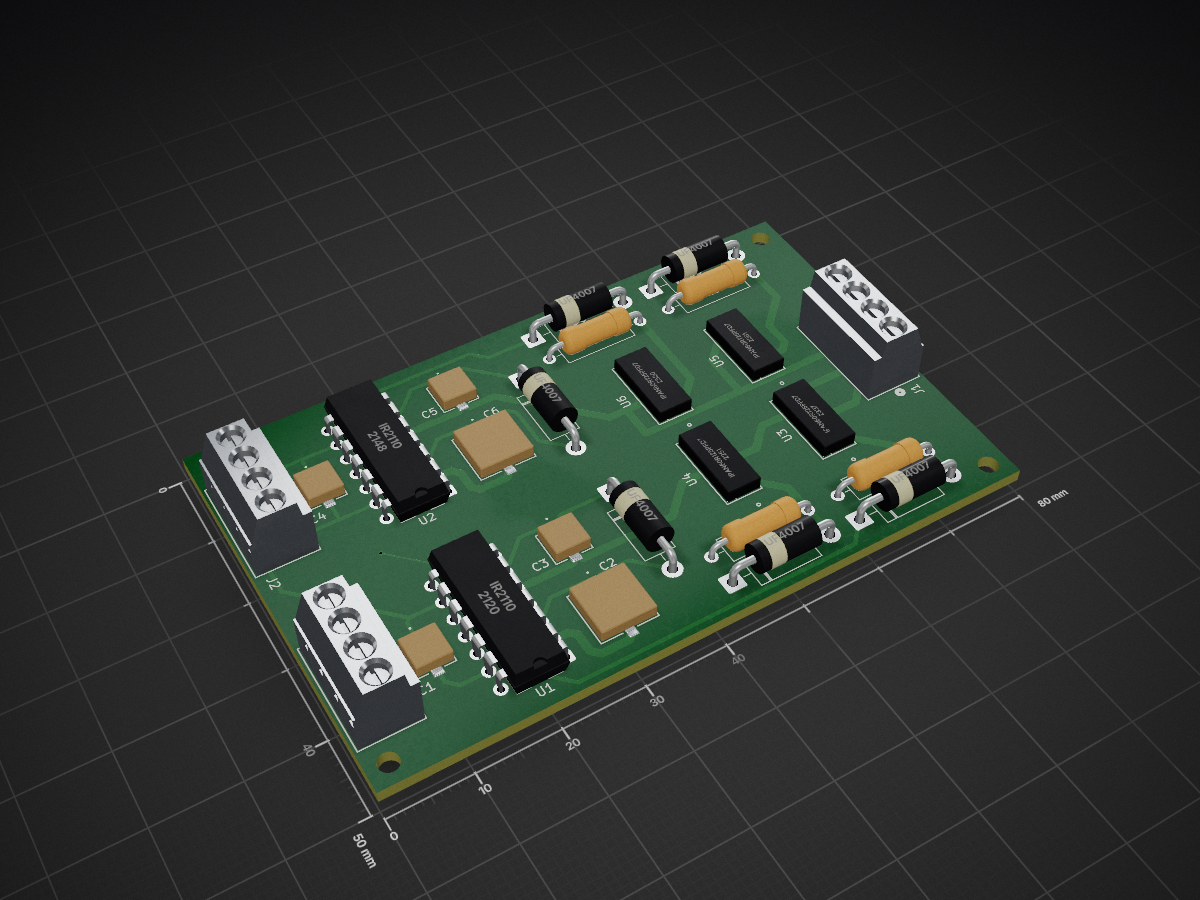
 allogic/MCTRL
A simple H-bridge driver board for various projects.
MCTRL is an open-source printed circuit board by allogic, from the allogic/MCTRL repository on GitHub, published under the MIT licence. It is a 2-layer board of 80 × 50 mm with 25 parts on 28 nets, routed with 277 tracks and 1 via.
It is built around the IR2110L4, IPAN60R125PFD7SXKSA1 and UF4007. Its parts include 6 capacitors, 6 ICs, 6 diodes, 4 resistors and 3 connectors.


| Qty | Value | Footprint | References |
|---|---|---|---|
| 6 | UF4007 | Diode_THT:D_DO-15_P12.70mm_Horizontal | D1, D2, D3, D4, D5, D6 |
| 4 | 100 | Resistor_THT:R_Axial_DIN0309_L9.0mm_D3.2mm_P12.70mm_Horizontal | R1, R2, R3, R4 |
| 4 | IPAN60R125PFD7SXKSA1 | MCTRL:IPAN60R125PFD7SXKSA1 | U3, U4, U5, U6 |
| 3 | 393570004 | MCTRL:393570004 | J1, J2, J3 |
| 2 | 100n | MCTRL:UUP1H0R1MCL1GS | C1, C4 |
| 2 | 220n | MCTRL:UWP1HR22MCL1GB | C3, C5 |
| 2 | 22u | MCTRL:EEEFK1H220P | C2, C6 |
| 2 | IR2110 | Package_DIP:DIP-14_W7.62mm | U1, U2 |
It measures 80 × 50 mm and has 2 copper layers, 1.6 mm thick.
25 parts, built around the IR2110L4, IPAN60R125PFD7SXKSA1 and UF4007. The full list of its parts is on this page, with links to each part's symbol and footprint where PCBKit's library has them.
From the allogic/MCTRL repository on GitHub, at the commit this page was made from: the board is MCTRL_HW/MCTRL.kicad_pcb and its schematic MCTRL_HW/MCTRL.kicad_sch. PCBKit opens the board in the browser, with nothing to install.
Its repository publishes it under the MIT licence: you may reuse it on that licence's terms (keep the author's notice, and for a copyleft licence share your changes alike).
mofaa69/modified-sine-inverter-gwo-pid
TÜBİTAK 2209-A Destekli GWO-PID Kontrollü Modifiye Sinüs İnverter Tasarımı ve Uygulaması

omerkarslioglu/forward_converter_pi_control
9-36V Input Voltage, 28 Output Voltage, All Ripple: %2, 50KHz, 50 Watt DC-DC Forward Converter Design And Production


cclienti/tig-welder
A DIY TIG welder that can be plugged to a traditionnal stick welder or to a high current source

arcoslab/open-coroco-legacy
COmpliant RObot COntroller is a free software project aiming to create an impedance controller based on a stm32 microcontroller using bldc motors and strain gauges.

chgopireddy/Full-Bridge-Class-D-Audio-Amplifier
LTspice Model for Full Bridge Class D, Voltage Mode Control, Peak Current Mode Control

AssaadMH/sensorless-bldc-control
Spinning a brushless motor with no position sensor — commutating on the back-EMF zero crossings instead.