4 layers52.2 × 88.4 mm
Variable Buck Converter
suryathanush/GanFET-Buck-Converter
LMG1210 driver based GANFET Buck converter with option for Changing inductor and PWM frequency and Duty Cycle Control signal through Raspberry Pi Pico
68 parts

 aliihsan1913/Project-Ares
This repository contains the conceptual hardware design files for the high-power RF generator and the software source code for the simulation engine.
Marssiklot is an open-source printed circuit board by aliihsan1913, from the aliihsan1913/Project-Ares repository on GitHub. It is a 4-layer board with 14 parts on 48 nets, routed with 45 tracks and 10 vias.
It is built around the LMG1210RVRT, SI7141DP and SI5351A-B-GM. Its parts include 6 capacitors, 3 connectors, 2 transistors, 1 IC and 1 inductor.


This project is an engineering simulation created strictly for fun and entertainment. To be completely honest, no physical RF plasma generator has been manufactured, and this system is not intended for actual deployment. Everything presented here is a theoretical "what-if" scenario and a creative exercise in conceptual hardware design and software simulation.
Project Ares is a cyber-physical system (CPS) testbed designed to simulate a 13.56 MHz RF Plasma Generator for Inductively Coupled Plasma (ICP) applications.
This repository contains the conceptual hardware design files for the high-power RF generator and the software source code for the simulation engine.
The theoretical hardware component focuses on generating high voltage switching power while maintaining strict signal integrity and thermal management.
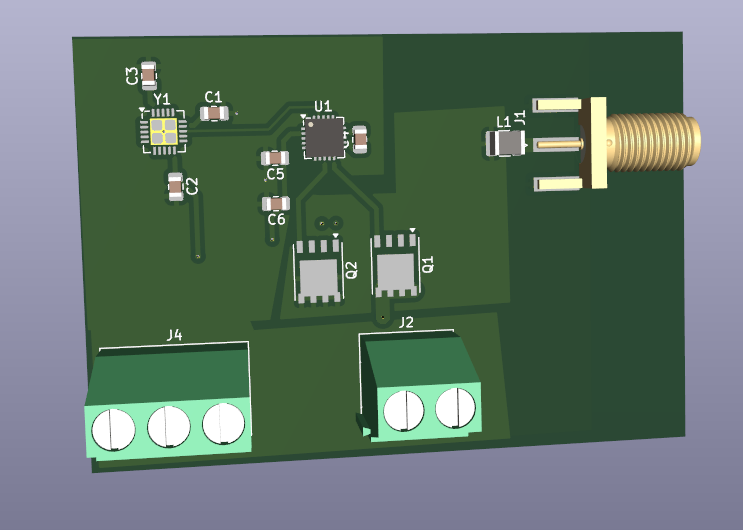
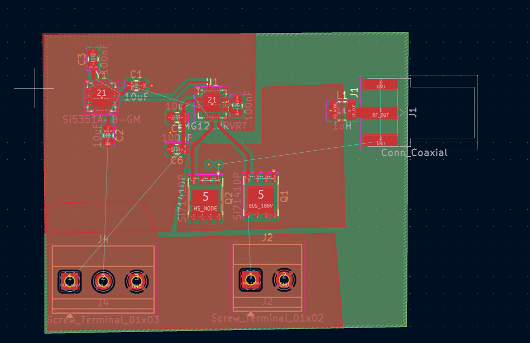
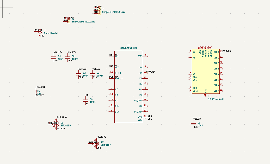
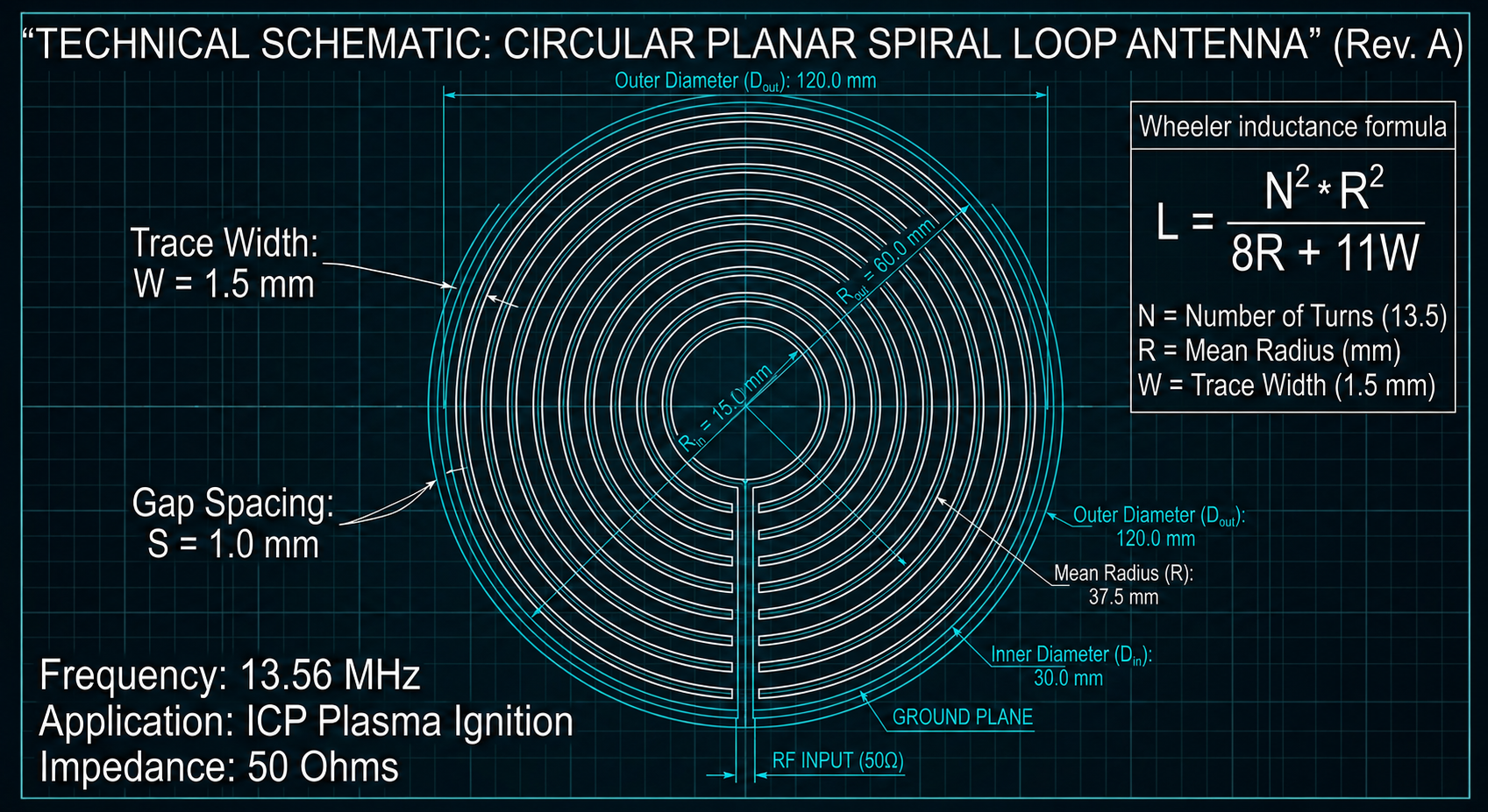
The software side consists of deterministic physics and visualization scripts running on Python and Pygame. Please note that Artificial Intelligence was used to assist in writing and structuring the software code for this simulation.
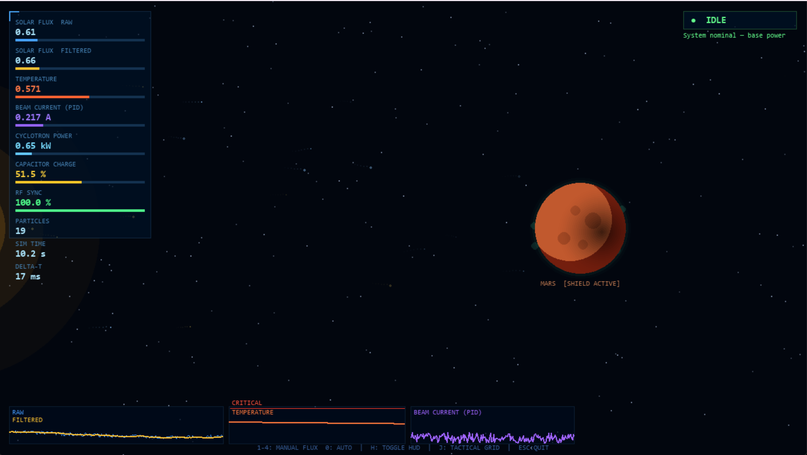
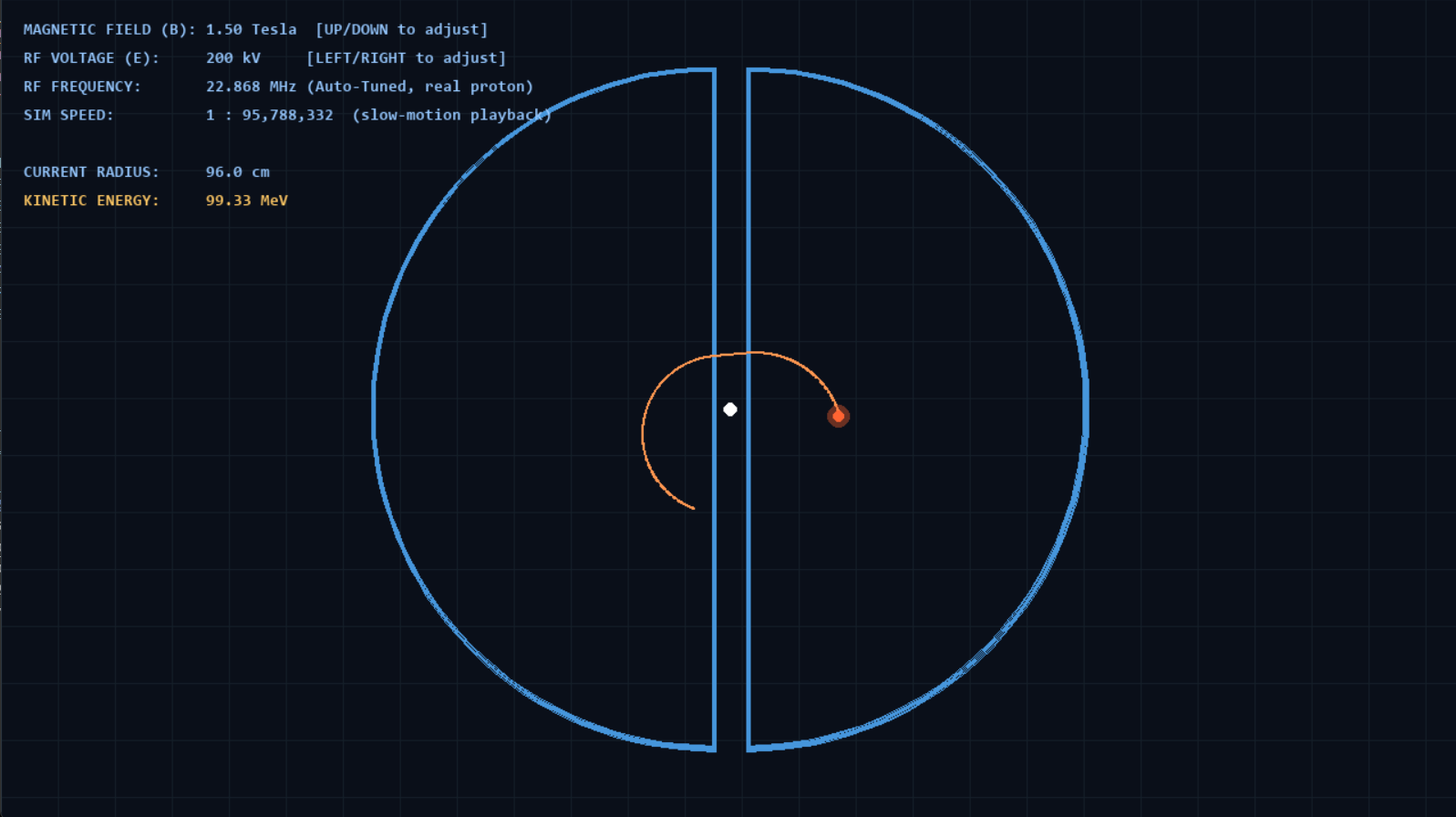
The repository is organized into specific directories for hardware, software, and imagery.
The hardware directory contains the KiCad project files, specifically fp-info-cache, marssiklot.kicad_pcb, marssiklot.kicad_prl, marssiklot.kicad_pro, and marssiklot.kicad_sch.
The software directory contains the core simulation scripts, which include cyclotrone.py, Aresgame.py, and Aressimu.py.
Ares/
├── Hardware/
│   ├── fp-info-cache
│   ├── marssiklot.kicad_pcb
│   ├── marssiklot.kicad_prl
│   ├── marssiklot.kicad_pro
│   └── marssiklot.kicad_sch
├── Images/
│   ├── Antenna.png
│   ├── CyclotroneSim.png
│   ├── Ares_RF.png
│   ├── Ares_RF_PCB.png
│   ├── SchemaAres.png
│   └── Sim_Screen.png
└── Software/
    ├── cyclotrone.py
    ├── Aresgame.py
└── Aressimu.py| Qty | Value | Footprint | References |
|---|---|---|---|
| 3 | 100nF | Capacitor_SMD:C_0805_2012Metric | C3, C4, C6 |
| 3 | 10uF | Capacitor_SMD:C_0805_2012Metric | C1, C2, C5 |
| 2 | Si7141DP | Package_SO:PowerPAK_SO-8_Single | Q1, Q2 |
| 1 | 1uH | Inductor_SMD:L_1210_3225Metric | L1 |
| 1 | Conn_Coaxial | Connector_Coaxial:SMA_Amphenol_132289_EdgeMount | J1 |
| 1 | LMG1210RVRT | Package_DFN_QFN:QFN-20-1EP_4x4mm_P0.5mm_EP2.5x2.5mm | U1 |
| 1 | Screw_Terminal_01x02 | TerminalBlock_Phoenix:TerminalBlock_Phoenix_MKDS-1,5-2_1x02_P5.00mm_Horizontal | J2 |
| 1 | Screw_Terminal_01x03 | TerminalBlock_Phoenix:TerminalBlock_Phoenix_MKDS-1,5-3_1x03_P5.00mm_Horizontal | J4 |
| 1 | Si5351A-B-GM | Package_DFN_QFN:QFN-20-1EP_4x4mm_P0.5mm_EP2.7x2.7mm | Y1 |
suryathanush/GanFET-Buck-Converter
LMG1210 driver based GANFET Buck converter with option for Changing inductor and PWM frequency and Duty Cycle Control signal through Raspberry Pi Pico

DRWJSCHMIDT/T41
This is the repository for the officially released V10, V11, and V12 versions of the T41 Software Defined Transceiver hardware and kits.


artificer123/Microwave_SDR_PCB
Collection of files used in development of a Xilinx Zynq based SDR with transverters for the V/UHF bands


14 parts, built around the LMG1210RVRT, SI7141DP and SI5351A-B-GM. The full list of its parts is on this page, with links to each part's symbol and footprint where PCBKit's library has them.
From the aliihsan1913/Project-Ares repository on GitHub, at the commit this page was made from: the board is Hardware/marssiklot.kicad_pcb and its schematic Hardware/marssiklot.kicad_sch. PCBKit opens the board in the browser, with nothing to install.
Its repository states no licence, so its author keeps all rights: ask aliihsan1913 before reusing the design.