4 layers38.1 × 25.4 mm

 alienware-sa/harness_tester_challenge
Harness Tester Challenge Leaderboard · comma.ai/jobs · Discord · X
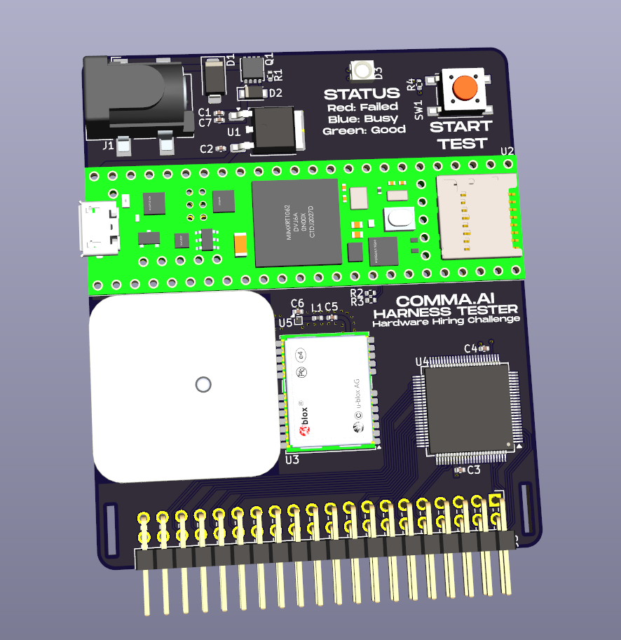
Hardware challenge is an open-source printed circuit board by alienware-sa, from the alienware-sa/harness_tester_challenge repository on GitHub, published under the MIT licence. It is a 4-layer board of 61 × 71 mm with 25 parts on 142 nets, routed with 577 tracks and 258 vias.
It is built around the TEENSY 4.1, CY8C9560A-24AXIT and L7805, with the NEO-M8N, ANT-GNSSCP-TH25L1 and ASMB-KTF0-0A306 among its other parts. Its parts include 7 capacitors, 5 ICs, 4 resistors, 3 diodes and 2 connectors. It belongs with the NXP (LPC, Kinetis, i.MX RT) boards of this library.


We (mock) designed a simple harness testing PCB and wrote some firmware for it. Unfortunately, this board was designed and firmware was written on a Monday morning.
Can you figure out everything wrong with it?
We currently sell hundreds of car-specific harnesses to users every month, consisting of close to 40 different types.
As a simple wiring harness, we expect them to have a near-zero failure rate. For this, making sure that the harness wiring matches the designed diagram for each unit we send out is vital. This tester is designed to be capable of quickly verifying which pins are connected to which other pins.
A quick list of design goals is listed here:
The challenge consists of 3 distinct parts, each riddled with a few bugs:
The web views are made possible thanks to KiCanvas!
The board is designed in KiCad 8, a free and open source EDA tool. The full project is available in an exported archive.
There are a handful of intentional, show-stopping bugs hidden in each part (we're not looking for potential points of improvement). Find them, and send them over to us for verification!
| Qty | Value | Footprint | References |
|---|---|---|---|
| 4 | 100n | Capacitor_SMD:C_0402_1005Metric | C2, C3, C4, C5 |
| 2 | 4k7 | Resistor_SMD:R_0402_1005Metric | R2, R3 |
| 1 | 10k | Resistor_SMD:R_0402_1005Metric | R4 |
| 1 | 10u | Capacitor_SMD:C_0402_1005Metric | C7 |
| 1 | 12V INPUT | Connector_BarrelJack:BarrelJack_CLIFF_FC681465S_SMT_Horizontal | J1 |
| 1 | 12n | Inductor_SMD:L_0402_1005Metric | L1 |
| 1 | 1k | Resistor_SMD:R_0402_1005Metric | R1 |
| 1 | 1n | Capacitor_SMD:C_0402_1005Metric | C6 |
| 1 | 1u | Capacitor_SMD:C_0402_1005Metric | C1 |
| 1 | ANT-GNSSCP-TH25L1 | gnss:ANT-GNSSCP-TH25L1 | AE1 |
| 1 | ASMB-KTF0-0A306 | LED_SMD:LED_ASMB-KTF0-0A306 | D3 |
| 1 | CY8C9560A-24AXIT | Package_QFP:TQFP-100_12x12mm_P0.4mm | U4 |
| 1 | Cable header | Connector_PinHeader_2.54mm:PinHeader_2x20_P2.54mm_Horizontal | J3 |
| 1 | L7805 | Package_TO_SOT_SMD:TO-252-2 | U1 |
| 1 | MAX2679 | Package_BGA:WLP-4_0.83x0.83mm_P0.4mm | U5 |
| 1 | NEO-M8N | RF_GPS:ublox_NEO | U3 |
| 1 | PMEG10020ELR | Diode_SMD:Nexperia_CFP3_SOD-123W | D2 |
| 1 | SMAJ16A | Diode_SMD:D_SMA | D1 |
| 1 | SiSS27DN | Package_SO:Vishay_PowerPAK_1212-8_Single | Q1 |
| 1 | TEST BUTTON | Button_Switch_SMD:SW_SPST_PTS645 | SW1 |
| 1 | Teensy4.1 | teensy:Teensy41 | U2 |


snorkman88/suntastic
An ultra low-power management board for IoT devices


UChicago-Space-Program/pulse-hardware
This is the central repository for documents related to PULSE-A hardware development.
It measures 61 × 71 mm and has 4 copper layers, 1.63 mm thick.
25 parts, built around the TEENSY 4.1, CY8C9560A-24AXIT, L7805 and NEO-M8N. The full list of its parts is on this page, with links to each part's symbol and footprint where PCBKit's library has them.
From the alienware-sa/harness_tester_challenge repository on GitHub, at the commit this page was made from: the board is kicad_files/hardware_challenge.kicad_pcb and its schematic kicad_files/hardware_challenge.kicad_sch. PCBKit opens the board in the browser, with nothing to install.
Its repository publishes it under the MIT licence: you may reuse it on that licence's terms (keep the author's notice, and for a copyleft licence share your changes alike).