4 layers299 × 127 mm

 aliadnani/antidote12
Budget neural amp modelling on a Radxa Cubie A7Z.
Antidote audio board is an open-source printed circuit board by aliadnani, from the aliadnani/antidote repository on GitHub, published under the Apache-2.0 licence. It is a 4-layer board of 65 × 30 mm with 62 parts on 67 nets, routed with 448 tracks and 154 vias.
It is built around the ADS1115IDGS and LP5907MFX-3.3. Its parts include 21 capacitors, 16 resistors, 6 connectors, 4 ICs and 2 diodes. It belongs with the audio and music boards of this library.



Budget neural amp modelling on a Radxa Cubie A7Z.
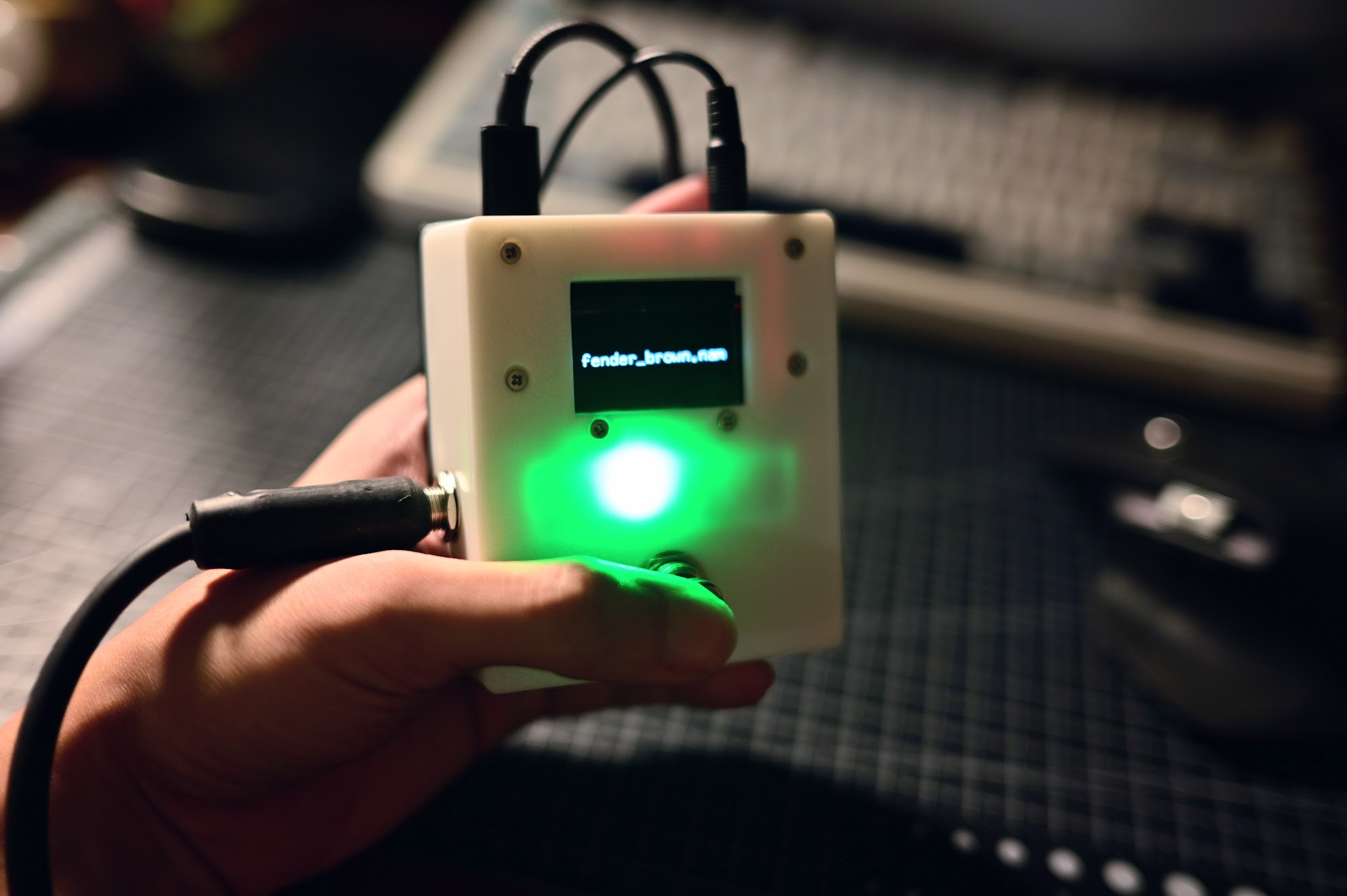
Neural Amp Modeler (NAM) uses neural networks to model guitar amplifiers from recorded input/output pairs, then reproduces their response on live guitar audio. I want to make a standalone guitar pedal for it.
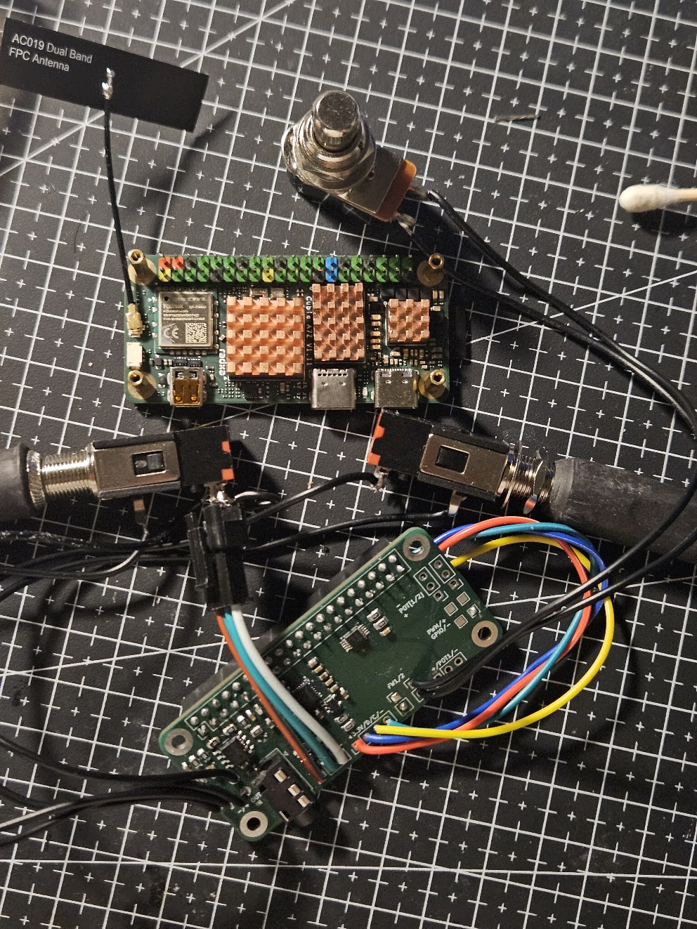
Rust firmware runs on a Radxa Cubie A7Z Linux SBC. It manages real-time audio capture and playback, including the hot loop that processes each buffer, wraps NAM A2’s C++ DSP library via FFI, and coordinates model loading and the pedal’s peripherals. A custom audio board provides instrument-level input and output.
The end goal is a budget, performant, standalone NAM pedal targetting buffers processed in under 10 ms (ideally under 5 ms) - essentially the threshold for human auditory latency perception.
src/: Rust firmware for audio processing, NAM A2 FFI, model loading, and pedal controls.hardware/: Schematics and PCB design files for the audio board + associated Linux device tree overlaysPlease see this repository as more of a reference design for what's possible and how such a pedal could be built, rather than a polished product.
Flash the SBC with Linux. Official Radxa images or community Armbian images should work fine.
Compile and load the driver for the audio board's codec (TAC5112).
make, then load the kernel module with insmod or modprobe.Compile and load the device tree overlay for the audio board.
./hardware/tac5112_i2c_i2s_overlay.dts. Compile it with dtc into a .dtbo file, then load it via rsetup.Configure the codec's ADC, DAC, and capture/playback paths if needed. These commands may be needed:
sudo amixer -c 0 cset name='ASI_RX_CH1_EN Switch' on
sudo amixer -c 0 cset name='OUT1x Source' 'DAC Input'
sudo amixer -c 0 cset name='OUT1x Config' 'Pseudo differential with OUTxM as VCOM'
sudo amixer -c 0 cset name='OUT1x Driver' 'Headphone'

sudo amixer -c 0 cset name='ASI_RX_CH2_EN Switch' on
sudo amixer -c 0 cset name='OUT2x Source' 'DAC Input'
sudo amixer -c 0 cset name='OUT2x Config' 'Mono Single-ended at OUTxP only'
sudo amixer -c 0 cset name='OUT2x Driver' 'Line-out'

sudo amixer -c 0 cset name='ADC1 Config' 'Single-ended'
sudo amixer -c 0 cset name='ADC1 Common-mode Tolerance' 'AC Coupled with 100mVpp'
sudo amixer -c 0 cset name='ADC1 Full-Scale' '2/10-VRMS'
sudo amixer -c 0 cset name='ASI_TX_CH1 Slot' 'Slot0'
sudo amixer -c 0 cset name='ASI_TX_CH1_EN Capture Switch' on
sudo amixer -c 0 cset name='ADC1 Digital Capture Volume' 161

sudo amixer -c 0 cset name='IN1 Source Mux' 'Analog'
sudo amixer -c 0 cset name='IN2 Source Mux' 'Analog'
Pull in the dependencies, then build the firmware in release mode on the SBC or cross-compile it on a host:
git submodule update --init --recursive
cargo build --release
Run the firmware in release mode, passing the directory containing your .nam models. If omitted, it uses resources/:
./target/release/antidote /path/to/nam/files
# Or:
cargo run --release -- /path/to/nam/files2026-09-25T16:57:33.860341Z INFO antidote: Starting Antidote.
2026-09-25T16:57:33.880659Z INFO antidote::modeller: Loaded NAM A2 model. model_path=resources/fender_brown.nam
2026-09-25T16:57:33.880875Z INFO antidote: Starting CPAL.
2026-09-25T16:57:33.989547Z INFO antidote: Playing back audio for 500 seconds.
2026-09-25T16:57:34.898597Z INFO antidote::audio: Audio errors input_drops=0 output_drops=0 output_underruns=320
2026-09-25T16:57:35.898842Z INFO antidote::audio: Audio errors input_drops=0 output_drops=0 output_underruns=320
2026-09-25T16:57:36.899102Z INFO antidote::audio: Audio errors input_drops=0 output_drops=0 output_underruns=320
...Once everything is working, some things you can do to make the pedal more usable:
systemd service to run the firmware on boot6.12+ kernel, you can use the play with the PREEMPT_RT to reduce latencymlockall and threadirqs, core pinning/isolation. You can push buffer sizes to around ~24 this way yielding a theorical round-trip latency of ~2ms.In principle, this project actually builds an entire hardware platform for any real-time guitar processing application for Linux SBCs. You can just as easily swap out the the firmware for another that runs say LV2/VST plugins. Though the main focus for this project is a standalone NAM pedal.
Built on top of:
| Qty | Value | Footprint | References |
|---|---|---|---|
| 8 | 1 uF | Capacitor_SMD:C_0603_1608Metric | C3, C8, C9, C10, C17, C18, C19, C20 |
| 7 | 0.1 uF | Capacitor_SMD:C_0603_1608Metric | C4, C6, C7, C11, C12, C13, C16 |
| 6 | 4.7 K | Resistor_SMD:R_0805_2012Metric | R1, R4, R8, R9, R12, R13 |
| 4 | 1 M | Resistor_SMD:R_0805_2012Metric | R2, R3, R6, R7 |
| 4 | 10 uF | Capacitor_SMD:C_0603_1608Metric | C1, C2, C15, C21 |
| 4 | MountingHole_Pad | MountingHole:MountingHole_2.7mm_M2.5_Pad | H1, H2, H3, H4 |
| 4 | TestPoint | TestPoint:TestPoint_Pad_1.5x1.5mm | TP1, TP2, TP3, TP4 |
| 3 | Potentiometer | Connector_PinHeader_2.54mm:PinHeader_1x03_P2.54mm_Vertical | RV1, RV2, RV3 |
| 2 | 200 R | Resistor_SMD:R_0805_2012Metric | R14, R15 |
| 2 | Footswitch | Connector_PinHeader_2.54mm:PinHeader_1x02_P2.54mm_Vertical | SW1, SW2 |
| 2 | LED | LED_SMD:LED_0805_2012Metric | D1, D2 |
| 1 | 1 K | Resistor_SMD:R_0805_2012Metric | R10 |
| 1 | 1 nF (DNP) | Capacitor_SMD:C_0603_1608Metric | C14 |
| 1 | 10 K | Resistor_SMD:R_0805_2012Metric | R16 |
| 1 | 100 K | Resistor_SMD:R_0805_2012Metric | R11 |
| 1 | 100 R | Resistor_SMD:R_0805_2012Metric | R5 |
| 1 | 100 pF | Capacitor_SMD:C_0603_1608Metric | C5 |
| 1 | ADS1115IDGS | Package_SO:TSSOP-10_3x3mm_P0.5mm | U1 |
| 1 | Cubie GPIO | Connector_PinHeader_2.54mm:PinHeader_2x20_P2.54mm_Vertical | J1 |
| 1 | I2C Header | Connector_PinHeader_2.54mm:PinHeader_1x04_P2.54mm_Vertical | J6 |
| 1 | Instrument In | Connector_Wire:SolderWire-0.5sqmm_1x02_P4.6mm_D0.9mm_OD2.1mm | J4 |
| 1 | Instrument Out | Connector_Wire:SolderWire-0.5sqmm_1x02_P4.6mm_D0.9mm_OD2.1mm | J2 |
| 1 | LED Header | Connector_PinHeader_2.54mm:PinHeader_1x03_P2.54mm_Vertical | J5 |
| 1 | LP5907MFX-3.3 | Package_TO_SOT_SMD:SOT-23-5 | U4 |
| 1 | MCP6002-xSN | Package_SO:SOIC-8_3.9x4.9mm_P1.27mm | U2 |
| 1 | Phones | Connector_Audio:Jack_3.5mm_PJ320E_Horizontal | J3 |
| 1 | TAC5112IRGER | easyeda2kicad:VQFN-24_L4.0-W4.0-P0.50-BL-EP2.1_1 | U3 |
It measures 65 × 30 mm and has 4 copper layers, 1.6 mm thick.
62 parts, built around the ADS1115IDGS and LP5907MFX-3.3. The full list of its parts is on this page, with links to each part's symbol and footprint where PCBKit's library has them.
From the aliadnani/antidote repository on GitHub, at the commit this page was made from: the board is hardware/antidote-audio-board/antidote-audio-board.kicad_pcb and its schematic hardware/antidote-audio-board/antidote-audio-board.kicad_sch. PCBKit opens the board in the browser, with nothing to install.
Its repository publishes it under the Apache-2.0 licence: you may reuse it on that licence's terms (keep the author's notice, and for a copyleft licence share your changes alike).

jerry20091103/Teensy_Grovebox
A portable synth and music multi-tool made with Teensy 4.1


Mew463/esp32-caliper
It features a built in 150mAh battery and a USB C interface for charging/uploading code.


will127534/RPI5-SDexpress-Hat
ctrl-c "RPI5-CFE-Hat" ctrl-v "RPI5-SDexpress-Hat"


ATmega8/kiterf
Release KiteRF is a SDR system with K210 & FPGA & ESP32 as its core controller, which make SDR more intelligent, portable and cheap.