4 layers28.2 × 26.1 mm
DongleHiderPlus PCB
LeoDJ/FW-EC-DongleHiderPlus
Framework Expansion Card that includes a USB hub to hide a bare dongle inside and still have a USB-A port externally
23 parts497CERN-OHL-W-2.0

 Alexei-Orlov/2526_Maker_Exercises
Exercices pour apprendre la modélisation 3D, l'impression 3D, la découpe à la laser, le routage et l'assemblage de PCB, le montage de batteries et la couture
Rasberry USB Port is an open-source printed circuit board by Alexei-Orlov, from the Alexei-Orlov/2526_Maker_Exercises repository on GitHub. It is a 4-layer board of 65 × 30 mm with 43 parts on 52 nets, routed with 358 tracks and 123 vias.
It is built around the USBLC6-2SC6 and CH334F. Its parts include 11 resistors, 9 connectors, 8 capacitors, 5 ICs and 5 diodes.


Exercices pour apprendre la modélisation 3D, l'impression 3D, la découpe à la laser, le routage et l'assemblage de PCB, le montage de batteries et la couture
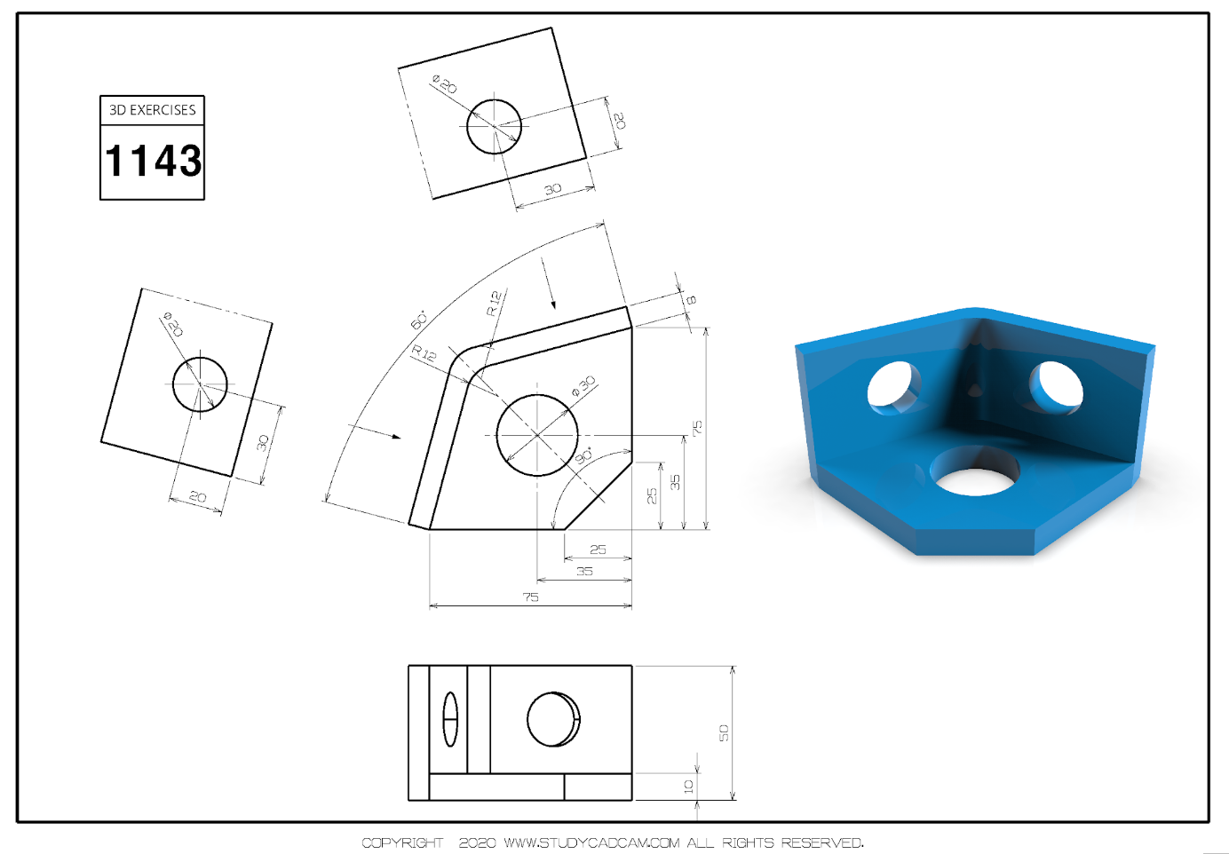
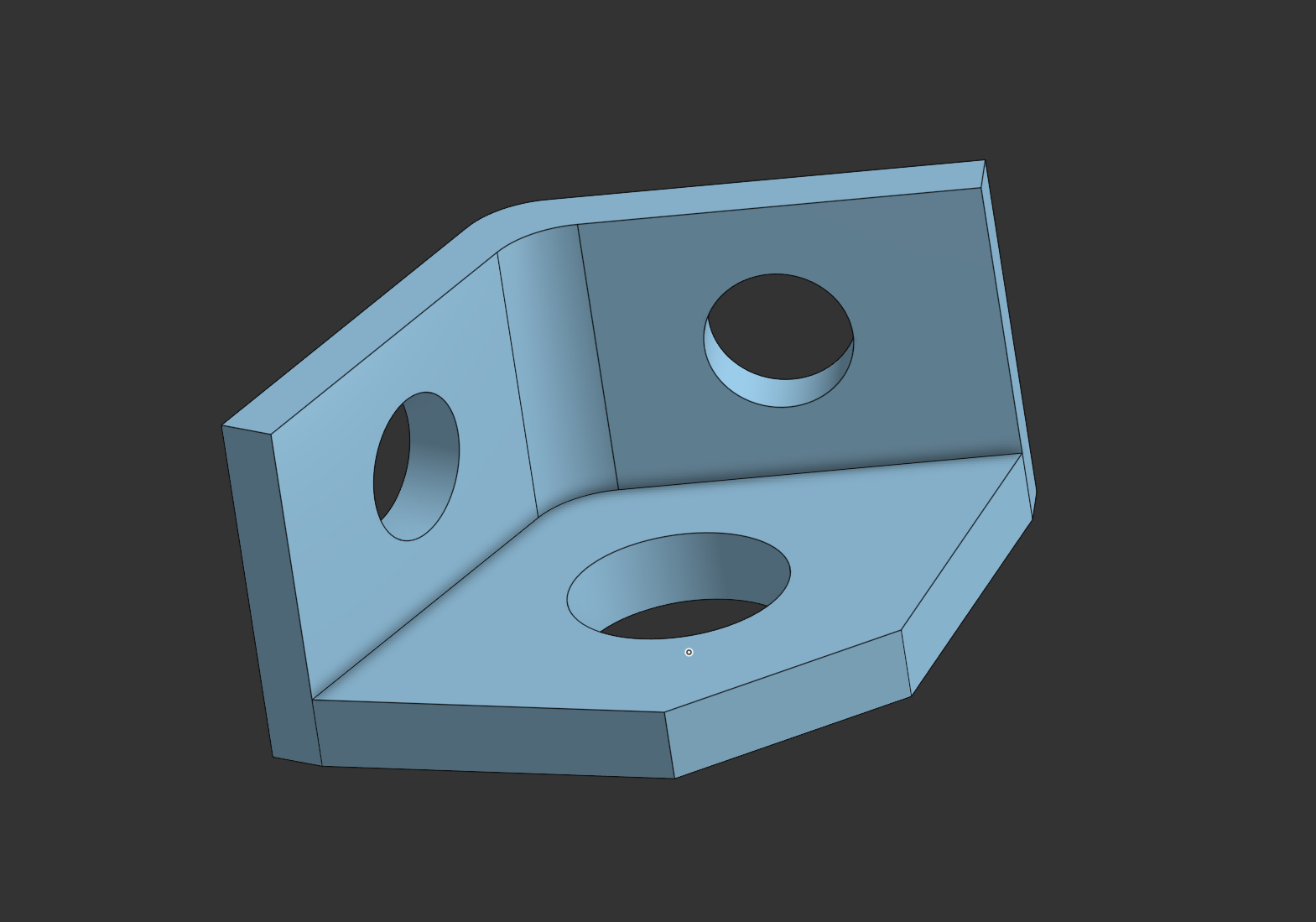
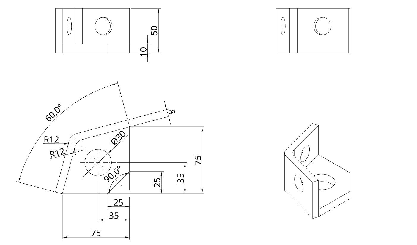
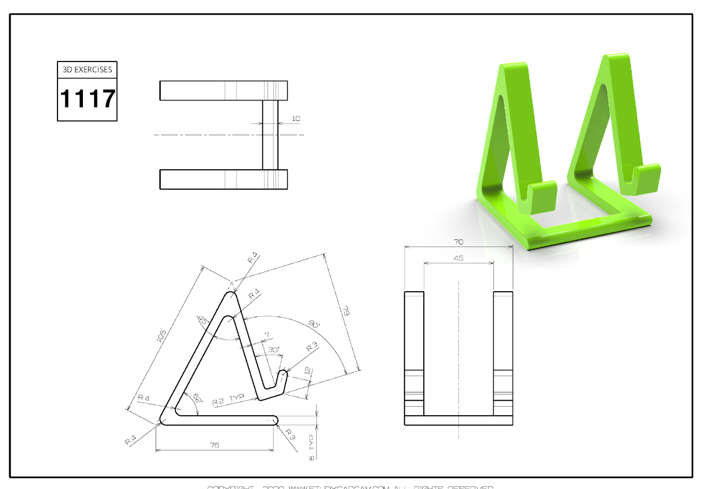
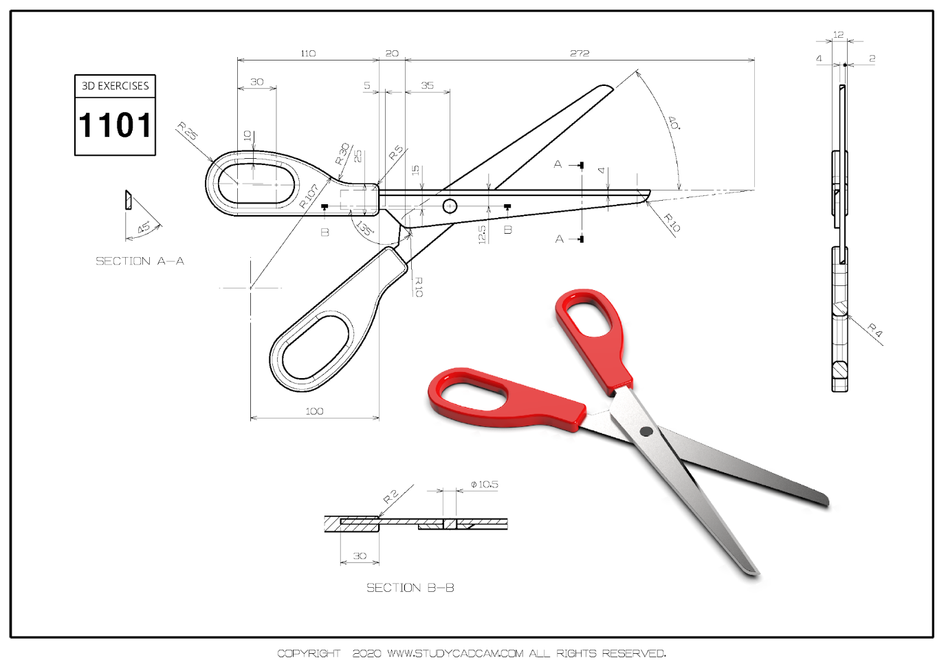
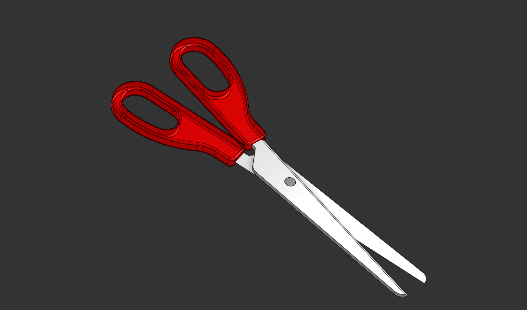
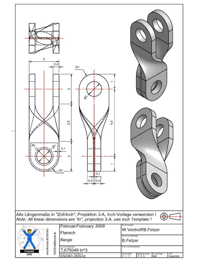
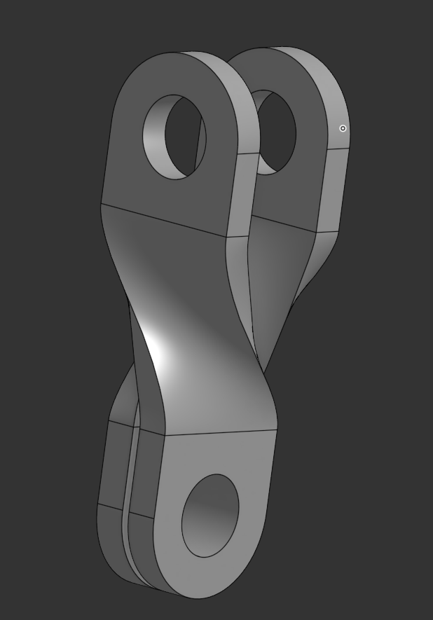
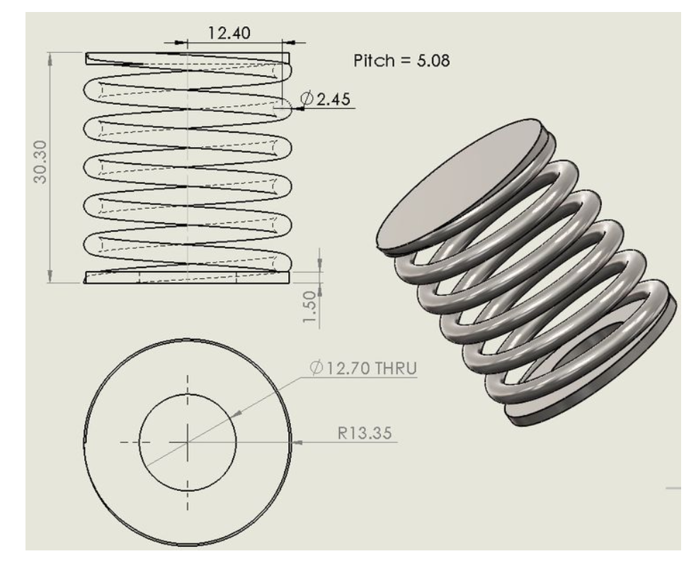
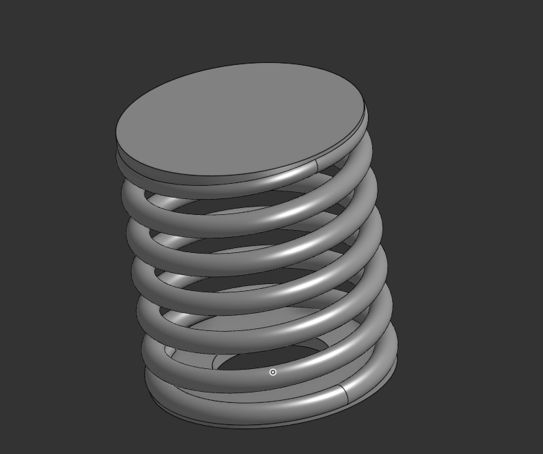
A l'aide du logiciel Onshape nous avons pour consigne de reproduire les modèles suivants :
 |  |
 |  |
 |  |
 |  |
 |  |
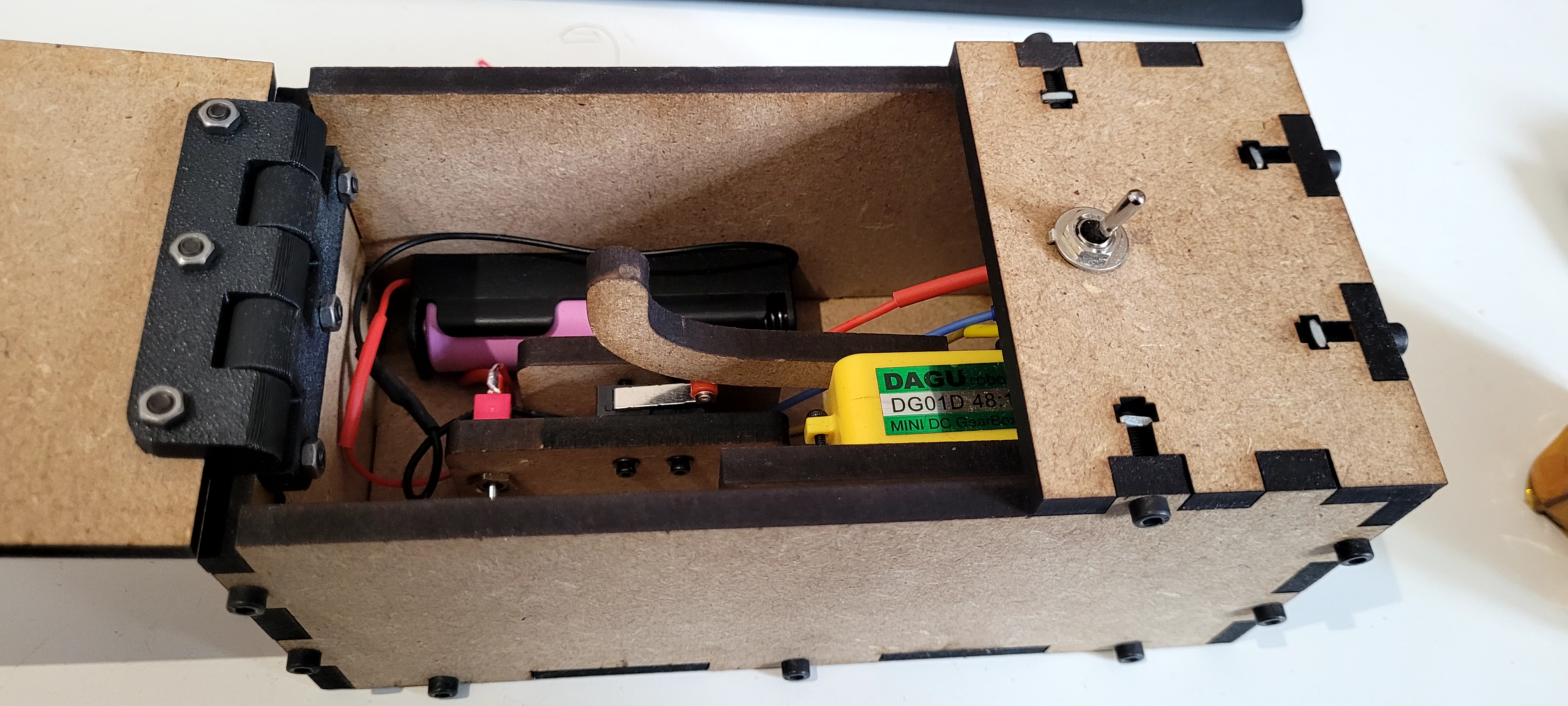
Useless Box : boite s'éteignant elle même à l'allumage.
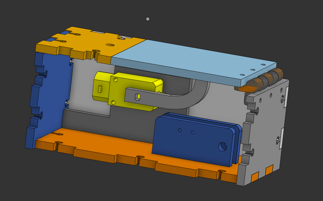
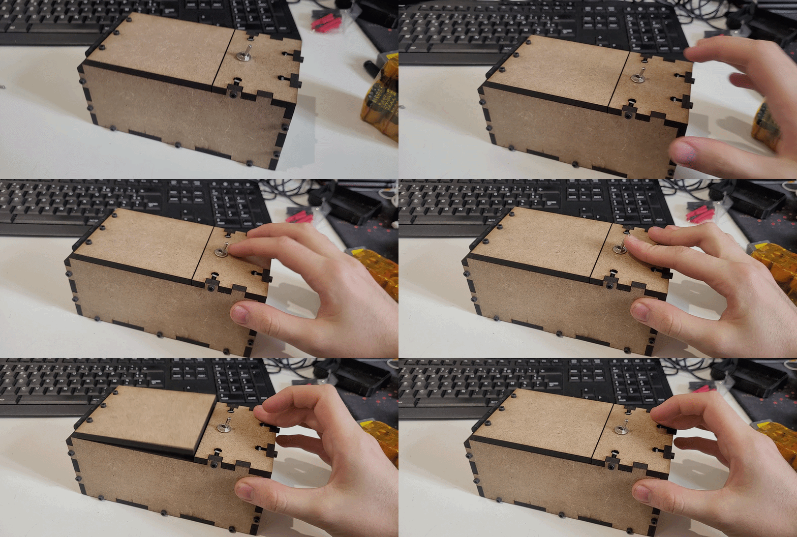
Un bouton supplémentaire permet de s'assurer que le moteur ne force pas de manière saccadée sur le bouton fin de cource pour se garder éteint
Création d'un hub USB pour Rasberry pi 0
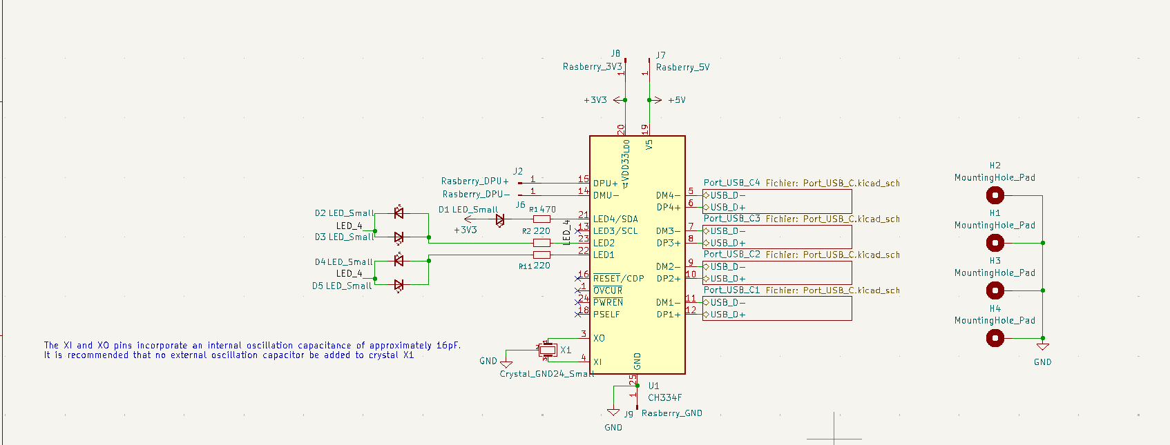
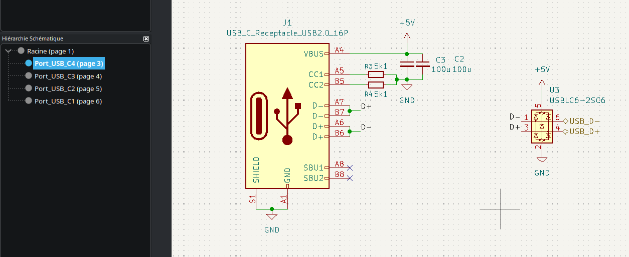
Erreurs connues : Les condensateur aux ports USB sont de 100uF pour permmettre de hot-plug le hub cela signifie qu'ils n'existent pas en 0402. Des décalages par rapport aux pogo pin de la pi sont aussi possibles.
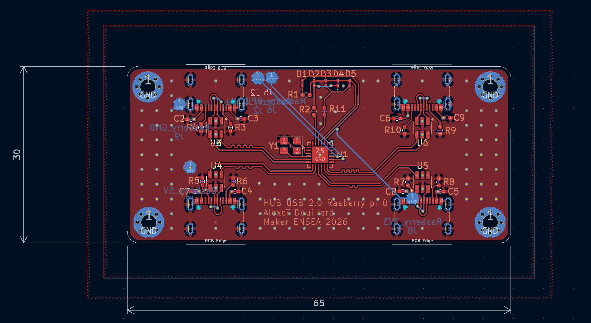
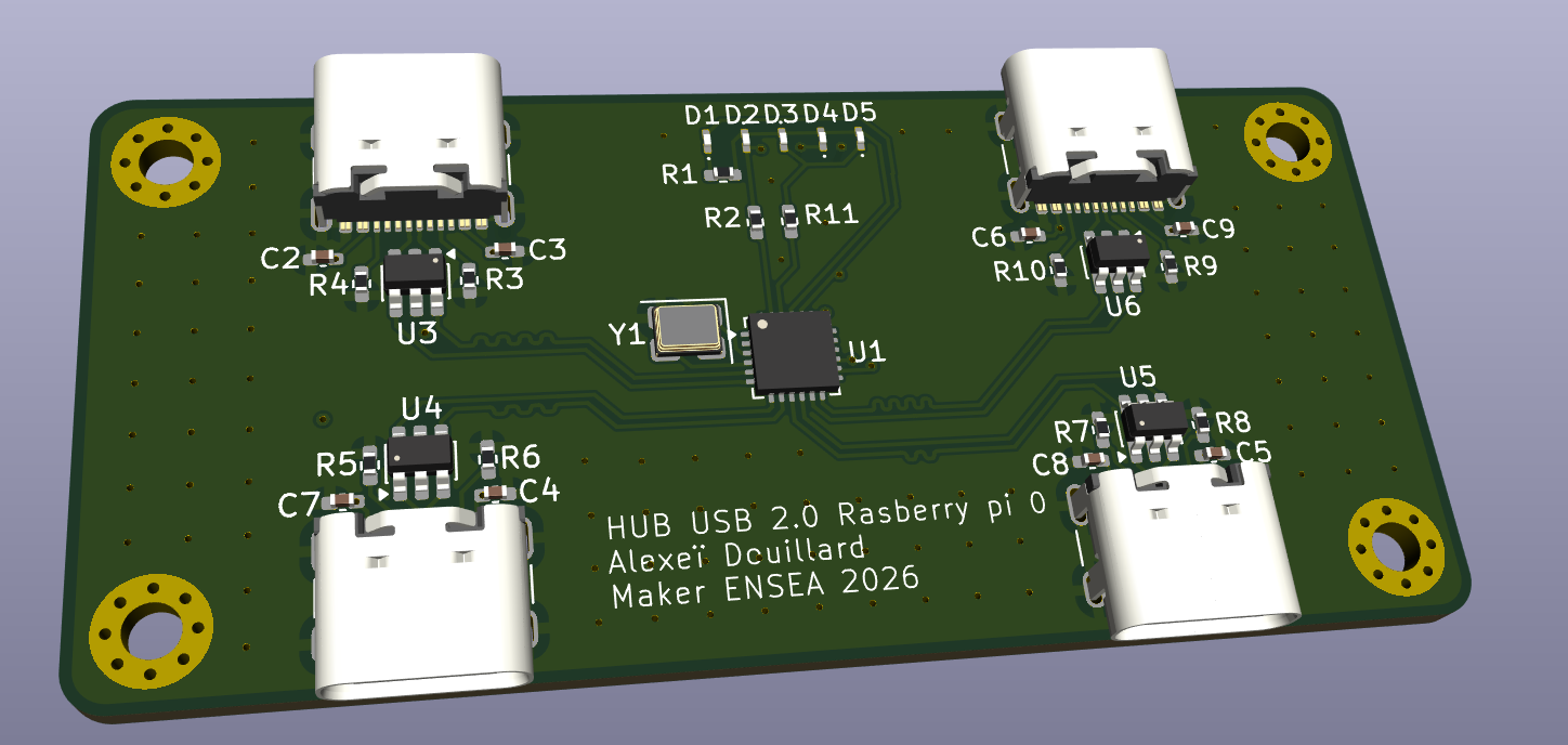
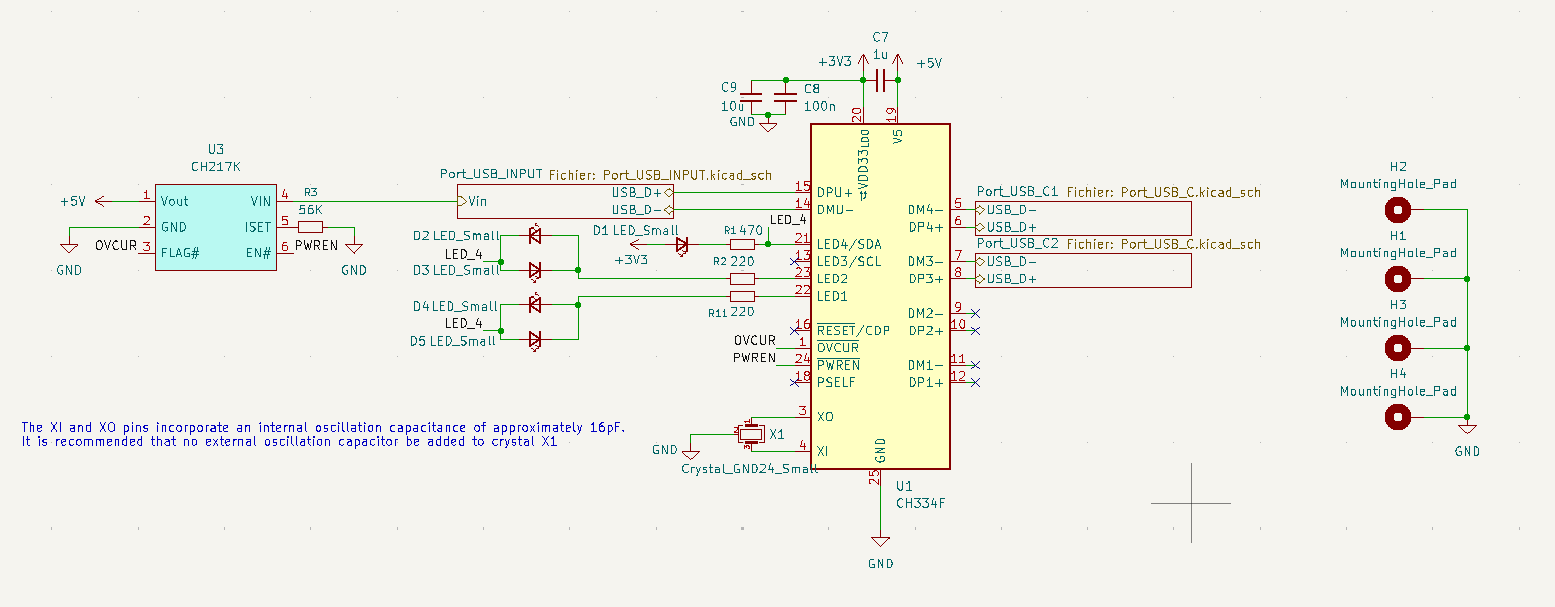
Je souhaite corriger ces erreurs et ajouter un module de protection de surcourants afin de réaliser un port USB compatibles avec les expansion modules de la marque Framework (W.I.P.)
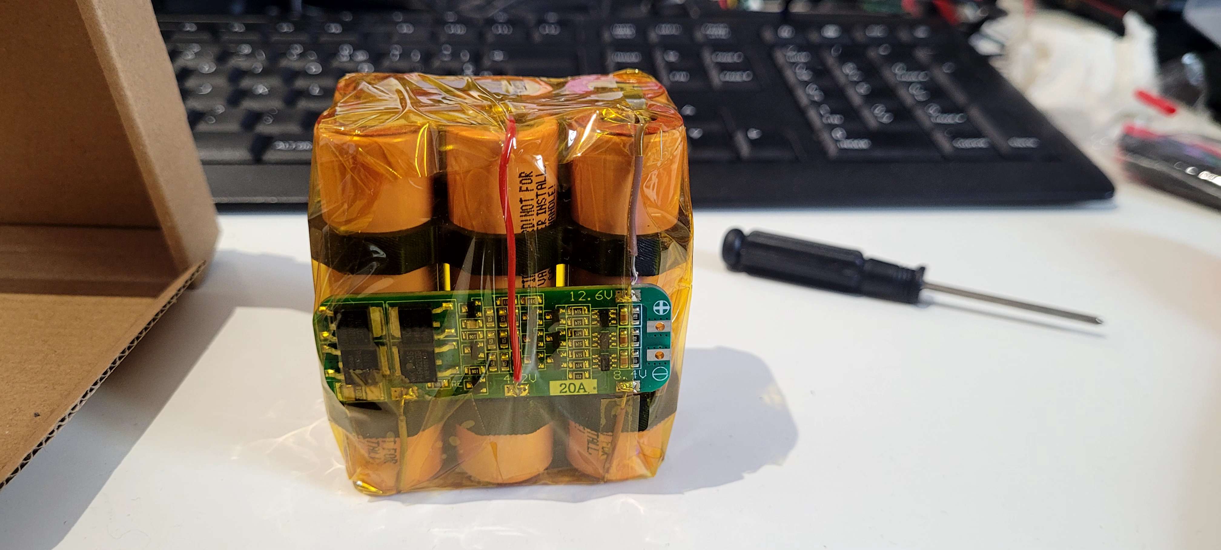
Montage d'une powebank 3s2p capable de charger des batteries 1s ou 2s (tension de sortie règlable avec limitation de courant)
En rouge la tension de la batterie et en bleu la tension de sortie réglable les 2 affichages peuvent êtres allumées ou éteints et l'ensemble de la powerbank peut être switché entre le mode charge (branché ici à un module buck boost USB) et son mode régulation de tension de sortie (sortie temporaire sur les 2 cables dupont bleu et orange)
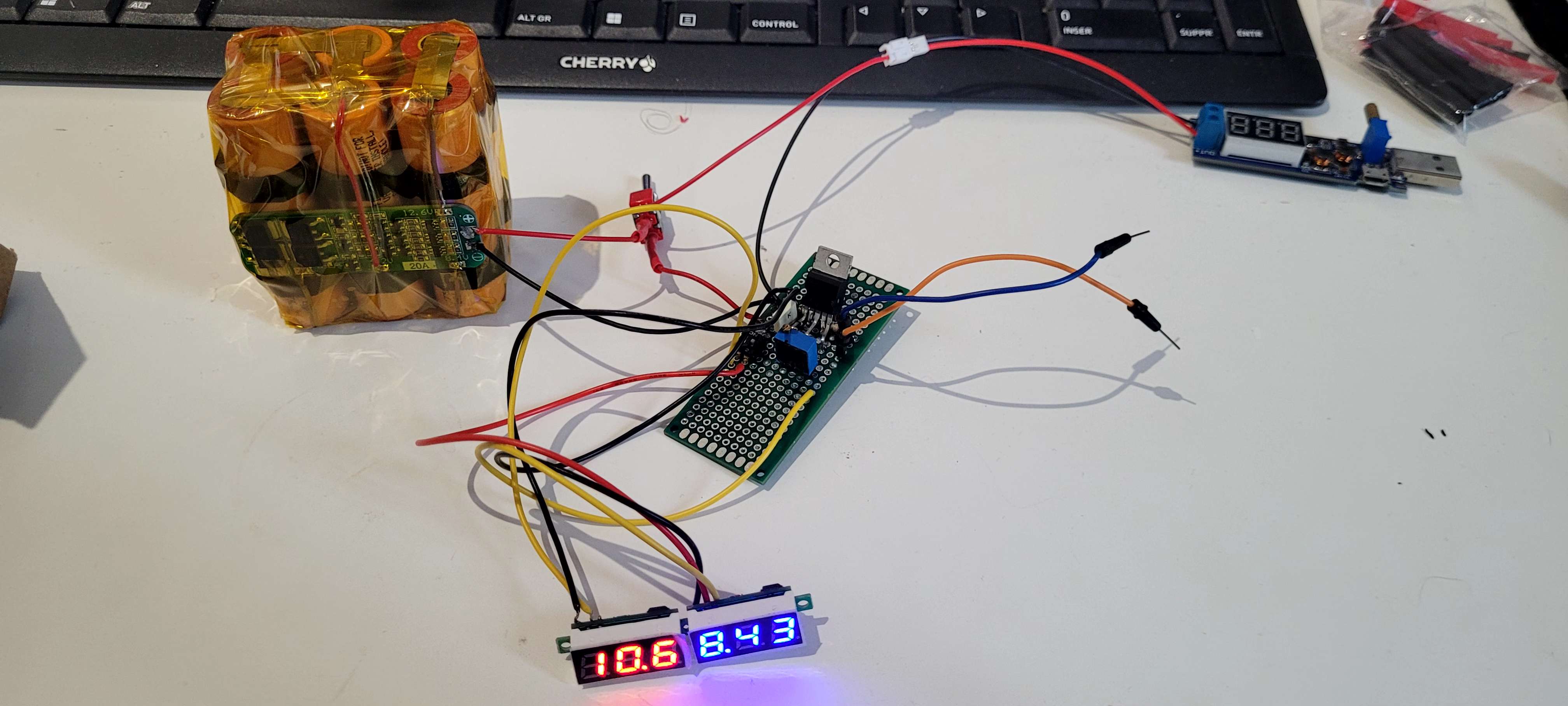
Le module utilisé pour la régulation du courant et de la tension est le L200 Pentawatt Le montage suivit est celui de la figure 27. La tension est réglé grâce au potentiomètre. Un boitier à imprimer en 3D est en cours de création pour ranger l'électronique plus proprement.
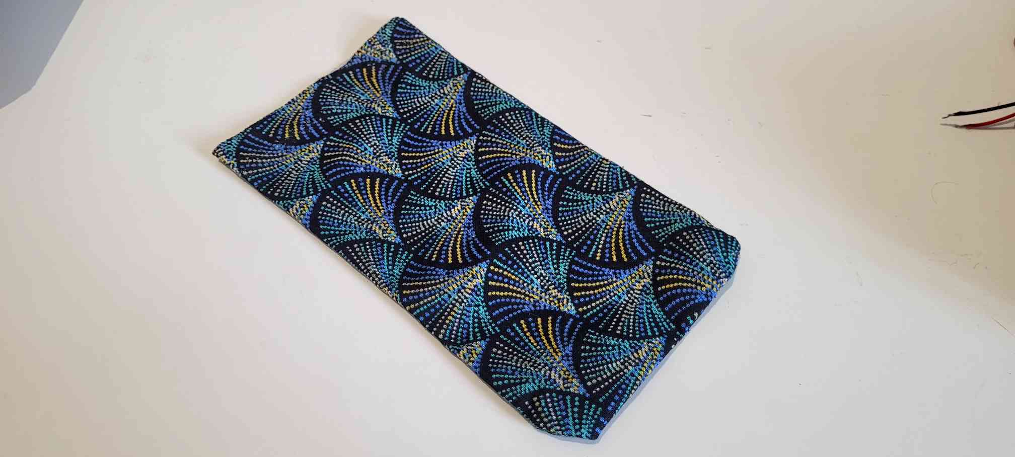
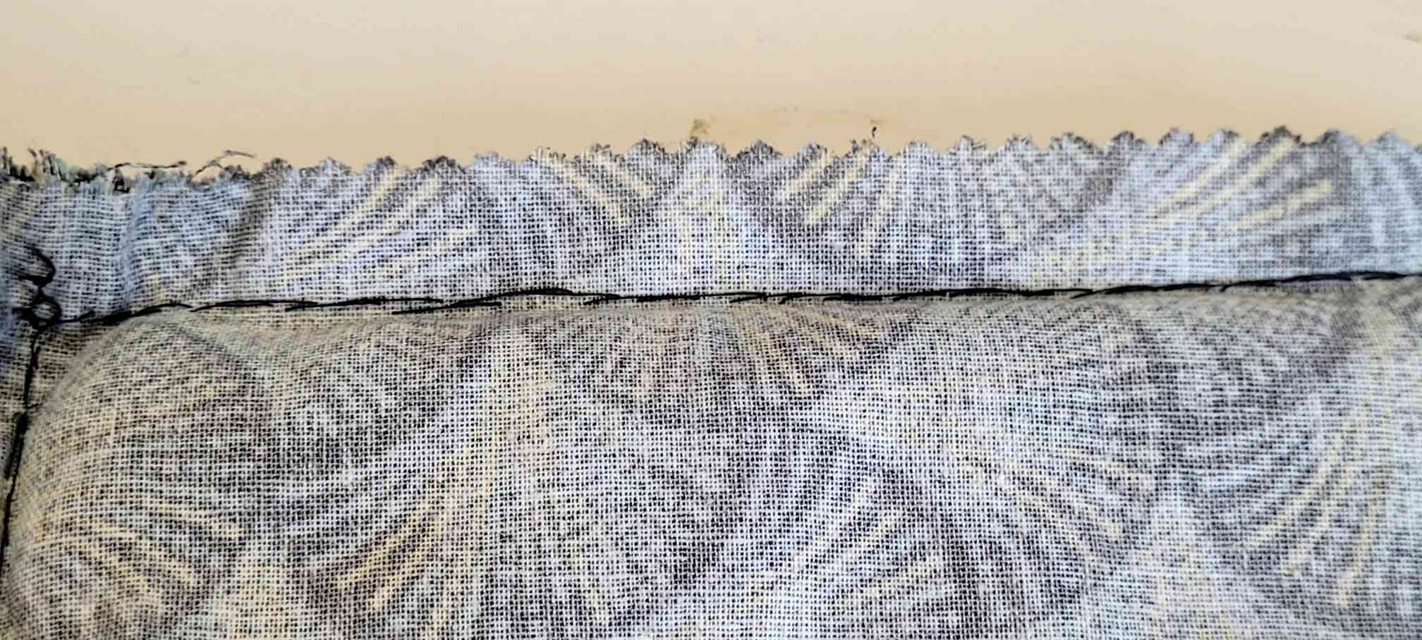
Poche pour téléphone cousue à la main
| Qty | Value | Footprint | References |
|---|---|---|---|
| 8 | 100u | Capacitor_SMD:C_0402_1005Metric_Pad0.74x0.62mm_HandSolder | C2, C3, C4, C5, C6, C7, C8, C9 |
| 8 | 5k1 | Resistor_SMD:R_0402_1005Metric_Pad0.72x0.64mm_HandSolder | R3, R4, R5, R6, R7, R8, R9, R10 |
| 5 | LED_Small | LED_SMD:LED_0201_0603Metric_Pad0.64x0.40mm_HandSolder | D1, D2, D3, D4, D5 |
| 4 | MountingHole_Pad | MountingHole:MountingHole_2.5mm_Pad_Via | H1, H2, H3, H4 |
| 4 | USBLC6-2SC6 | Package_TO_SOT_SMD:SOT-23-6 | U3, U4, U5, U6 |
| 4 | USB_C_Receptacle_USB2.0_16P | Connector_USB:USB_C_Receptacle_GCT_USB4105-xx-A_16P_TopMnt_Horizontal | J1, J3, J4, J5 |
| 2 | 220 | Resistor_SMD:R_0402_1005Metric_Pad0.72x0.64mm_HandSolder | R2, R11 |
| 1 | 470 | Resistor_SMD:R_0402_1005Metric_Pad0.72x0.64mm_HandSolder | R1 |
| 1 | CH334F | Package_DFN_QFN:QFN-24-1EP_4x4mm_P0.5mm_EP2.7x2.7mm | U1 |
| 1 | Crystal_GND24_Small | Crystal:Crystal_SMD_WE_CFPX-180-4Pin_3.2x2.5mm | Y1 |
| 1 | Rasberry_3V3 | USB_HUB_Library:Pogo pin | J8 |
| 1 | Rasberry_5V | USB_HUB_Library:Pogo pin | J7 |
| 1 | Rasberry_DPU+ | USB_HUB_Library:Pogo pin | J2 |
| 1 | Rasberry_DPU- | USB_HUB_Library:Pogo pin | J6 |
| 1 | Rasberry_GND | USB_HUB_Library:Pogo pin | J9 |
LeoDJ/FW-EC-DongleHiderPlus
Framework Expansion Card that includes a USB hub to hide a bare dongle inside and still have a USB-A port externally


gustebeast/public-steel-guitar
A pedal steel guitar you can build yourself, from parts anyone can buy.


emiz-jh/2526_Maker_ClawMachine
Projet de machine à pince réalisé dans le cadre de l'Option Maker ENSEA 2025-2026.

byrantech/laptop
anyon_e, a highly integrated, high end, open source laptop. Attempt the impossible.

i2cjak/Framework_Expansion_Cards
In which i2cjak creates a new expansion card design every day until he is given a NICE Framework laptop
It measures 65 × 30 mm and has 4 copper layers, 1.6 mm thick.
43 parts, built around the USBLC6-2SC6 and CH334F. The full list of its parts is on this page, with links to each part's symbol and footprint where PCBKit's library has them.
From the Alexei-Orlov/2526_Maker_Exercises repository on GitHub, at the commit this page was made from: the board is 04_PCB/Rasberry_USB_Port/Rasberry_USB_Port.kicad_pcb and its schematic 04_PCB/Rasberry_USB_Port/Port_USB_C.kicad_sch. PCBKit opens the board in the browser, with nothing to install.
Its repository states no licence, so its author keeps all rights: ask Alexei-Orlov before reusing the design.