2 layers32.5 × 19.1 mm
Stepper motor driver
alexandercote/Stepper_Motor_Controller
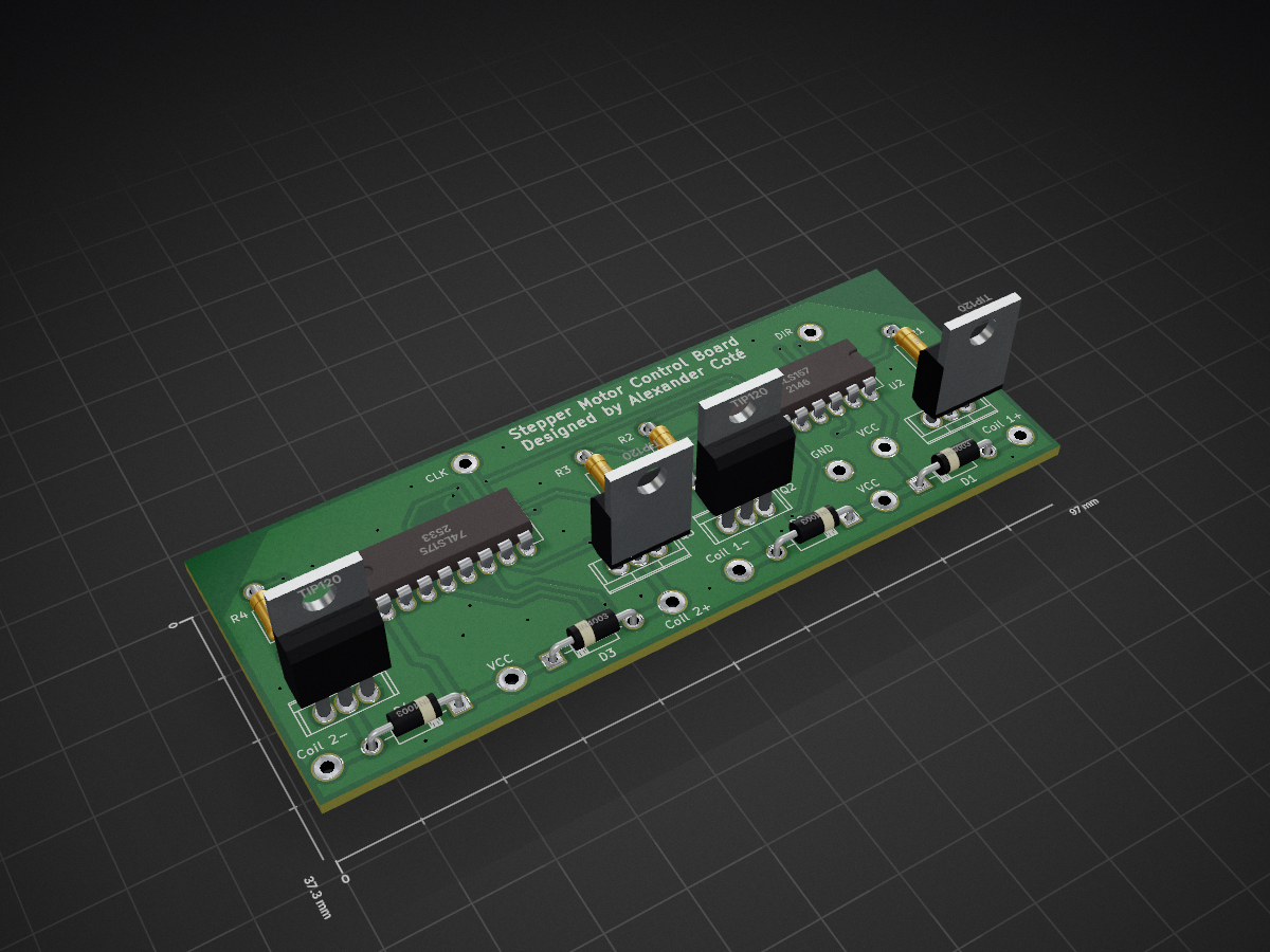
Designed a circuit board in KiCad to control the forward and reverse motion of a 6-wire stepper motor driver.
21 parts
 alexandercote/Stepper_Motor_Controller
Designed a circuit board in KiCad to control the forward and reverse motion of a 6-wire stepper motor driver.
Stepper motor driver is an open-source printed circuit board by alexandercote, from the alexandercote/Stepper_Motor_Controller repository on GitHub. It is a 2-layer board of 97 × 37.3 mm with 24 parts on 24 nets, routed with 199 tracks and 36 vias.
It is built around the 74LS157PC, 74LS175PC and TIP120. Its parts include 4 resistors, 4 diodes, 4 transistors and 2 ICs. It belongs with the robots and motor control boards of this library.


Designed a circuit board in KiCad to control the forward and reverse motion of a 6-wire stepper motor driver. The board uses an Arduino to control the direction. The board also requires a clock to modulate the motor speed.
The circuit schematic is presented below. It uses a quad D flip-flop followed by a quad two input multiplexer to control the positive and negative terminals of the two coils of the stepper motor.

The PCB was redesigned a year after to use SMD components and save space. It is a two layer board; the top and the bottom layer can be found below:
Top of the PCB:

Bottom of the PCB:

The first version of the board's PCB can be found below. It used all through hole components, and was used as a learning experience for KiCad and placement, and did not take into account the board's size.
Top of the PCB:

Bottom of the PCB:

| Qty | Value | Footprint | References |
|---|---|---|---|
| 10 | TEST_1P | Measurement_Points:Measurement_Point_Round-TH_Big | CLK, Coil 1-, Coil 1+, Coil 2-, Coil 2+, DIR, GND, VCC, VCC, VCC |
| 4 | 180 | Resistors_ThroughHole:Resistor_Horizontal_RM10mm | R1, R2, R3, R4 |
| 4 | 1N4003 | Diodes_ThroughHole:Diode_DO-41_SOD81_Horizontal_RM10 | D1, D2, D3, D4 |
| 4 | TIP120 | Power_Integrations:TO-220 | Q1, Q2, Q3, Q4 |
| 1 | 74LS157 | Housings_DIP:DIP-16_W7.62mm_LongPads | U2 |
| 1 | 74LS175 | Housings_DIP:DIP-16_W7.62mm_LongPads | U1 |
alexandercote/Stepper_Motor_Controller
Designed a circuit board in KiCad to control the forward and reverse motion of a 6-wire stepper motor driver.

RetroStack/TRS-80-Model-I-G-E1
Hardware Replica of the TRS-80 Model I Revision G

btb/80ColumnCard
An Apple II 80-Column Card. Based on the Videx Videoterm


clemarfolly/Microdigital-TK2000
Reprodução da PCB do TK-2000 da Microdigital, clone do Micro-Professor MPF-II


alvaroalea/QL_Trump2_clone
DIsc Interface for the Sinclair QL computer

schlae/AmdekDVM
Reverse engineering Amdek DVM video card for the Apple II

It measures 97 × 37.3 mm and has 2 copper layers, 1.6 mm thick.
24 parts, built around the 74LS157PC, 74LS175PC and TIP120. The full list of its parts is on this page, with links to each part's symbol and footprint where PCBKit's library has them.
From the alexandercote/Stepper_Motor_Controller repository on GitHub, at the commit this page was made from: the board is V1 - 2016 - Through-Hole/Stepper motor driver.kicad_pcb. PCBKit opens the board in the browser, with nothing to install.
Its repository states no licence, so its author keeps all rights: ask alexandercote before reusing the design.