2 layers56.5 × 64.8 mm
OPL2 VGM Player
AidanHockey5/YM3812_VGM_Player
A Video Game Music player based on the YM3812 (OPL2) and Teensy 3.5
14 parts72AGPL-3.0

 alexandercote/Alarm_Clock_Audio_Amp
Design class project where I worked in a group of 3 to implement a music playing alarm clock using a microcontroller board.
Alarm Clock V1 is an open-source printed circuit board by alexandercote, from the alexandercote/Alarm_Clock_Audio_Amp repository on GitHub. It is a 2-layer board of 69.1 × 73.9 mm with 88 parts on 148 nets, routed with 617 tracks and 6 vias.
It is built around the LM358N, LM386 and IRLIB9343PBF. Its parts include 33 resistors, 15 transistors, 12 capacitors, 6 connectors and 5 switches. It belongs with the lEDs and displays boards of this library.


Schematic view of the top hierarchy view, including push button debouncing, with an audio amplifier and LED multiplexer in lower hierarchy schematics.

Schematic view of the audio amplifier schematic. Includes a low pass filter cascaded with a high-pass filter, a potentiometer for input voltage control, and an LM386 to amplify.

The schematic view of the LED multiplexing circuit:

The PCB (Two layer):
Top layer PCB view:

Top layer view from the manufacturer (OshPark):

Bottom layer PCB view:
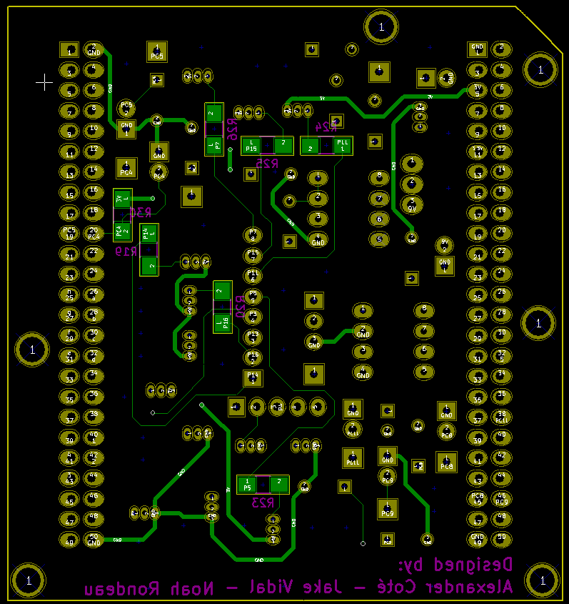 Bottom layer view from the manufacturer:

| Qty | Value | Footprint | References |
|---|---|---|---|
| 14 | 1 kΩ | Resistors_SMD:R_1206_HandSoldering | R5, R7, R8, R9, R10, R11, R12, R13, R14, R15, R16, R17, R18, R27 |
| 10 | 100 nF | Capacitors_ThroughHole:C_Rect_L7_W2.5_P5 | C2, C3, C4, C5, C6, C7, C8, C9, C11, C12 |
| 8 | 100 Ω | Resistors_SMD:R_1206_HandSoldering | R19, R20, R21, R22, R23, R24, R25, R26 |
| 8 | 2N3906 | TO_SOT_Packages_THT:TO-92_Inline_Narrow_Oval | Q2, Q4, Q5, Q7, Q8, Q9, Q11, Q12 |
| 8 | TEST_1P | Pin_Headers:Pin_Header_Straight_1x01 | W1, W2, W3, W4, W5, W6, W7, W8 |
| 6 | 2N3904 | TO_SOT_Packages_THT:TO-92_Inline_Narrow_Oval | Q3, Q6, Q10, Q13, Q14, Q15 |
| 5 | 47 kΩ | Resistors_SMD:R_1206_HandSoldering | R29, R30, R31, R32, R33 |
| 5 | SW_PUSH | Pin_Headers:Pin_Header_Straight_1x02 | SW1, SW2, SW3, SW4, SW5 |
| 2 | ECE:STM32_F4_ConnV2 | P4, P5 | |
| 2 | 120 kΩ | Resistors_SMD:R_1206_HandSoldering | R2, R3 |
| 2 | CONN_01X02 | Pin_Headers:Pin_Header_Straight_1x02 | P1, P6 |
| 1 | 10 uF | Capacitors_ThroughHole:C_Disc_D3_P2.5 | C1 |
| 1 | 10 Ω | Resistors_SMD:R_1206_HandSoldering | R6 |
| 1 | 100 kΩ | Resistors_SMD:R_1206_HandSoldering | R4 |
| 1 | 470 uF | Capacitors_ThroughHole:C_Disc_D7.5_P5 | C10 |
| 1 | 6.2 kΩ | Resistors_SMD:R_1206_HandSoldering | R28 |
| 1 | 82 Ω | Resistors_SMD:R_1206_HandSoldering | R1 |
| 1 | CONN_01X05 | Pin_Headers:Pin_Header_Straight_1x05 | P2 |
| 1 | CONN_01X08 | Pin_Headers:Pin_Header_Straight_1x08 | P3 |
| 1 | IRLIB9343 | Power_Integrations:TO-220 | Q1 |
| 1 | LM358N | Housings_DIP:DIP-8_W7.62mm_LongPads | U1 |
| 1 | LM386 | Housings_DIP:DIP-8_W7.62mm_LongPads | U2 |
| 1 | POT: 100 kΩ | Pin_Headers:Pin_Header_Straight_1x03 | RV1 |
The 82 most common of 88 parts.
AidanHockey5/YM3812_VGM_Player
A Video Game Music player based on the YM3812 (OPL2) and Teensy 3.5


kr4fty/DiySolderingStation
Diy Soldering Stations with Atmega (Arduino UNO). Firmware and hardware design included


It measures 69.1 × 73.9 mm and has 2 copper layers, 1.6 mm thick.
88 parts, built around the LM358N, LM386 and IRLIB9343PBF. The full list of its parts is on this page, with links to each part's symbol and footprint where PCBKit's library has them.
From the alexandercote/Alarm_Clock_Audio_Amp repository on GitHub, at the commit this page was made from: the board is PCB/Alarm Clock V1.kicad_pcb. PCBKit opens the board in the browser, with nothing to install.
Its repository states no licence, so its author keeps all rights: ask alexandercote before reusing the design.