Skip to the content
4 layers130 × 150 mmCampervan management V2, the printed circuit board in 3D

Campervan management V2

akladnig/CamperVan

- CamperVan Design and Arduino Circuit Design - Campervan Design Overview - Dashboard App - Electrical System - Sensors - Circuit Design - Battery and voltage monitoring - Voltage Divider Design - Low Pass Filter - TODO

Size
130 × 150 mm
Copper layers
4
Thickness
1.6 mm
Parts
183
Nets
127
Pads
556
Tracks, vias
921, 203
Pours
51
Routed
Yes
KiCad
KiCad 9.0 (file 20241229)
Created
30 Mar 2025
Updated
7 Oct 2025

Overview

Campervan management V2 is an open-source printed circuit board by akladnig, from the akladnig/CamperVan repository on GitHub. It is a 4-layer board of 130 × 150 mm with 183 parts on 127 nets, routed with 921 tracks and 203 vias.

It is built around the MAX487EPA+, RS485 and LM358DR2GH, with the LTV-817S-TA1-C, HCNR200-500E and FDS4685 among its other parts. Its parts include 58 resistors, 55 capacitors, 27 ICs, 11 connectors and 10 diodes. It belongs with the ESP32 and AVR (ATmega, ATtiny) boards of this library.

Main components

7

README

README.md

CamperVan Design and Arduino Circuit Design

Campervan Design Overview

I used OpenScad to do the campervan design. Whilst I have used SketchUp in the past OpenScad appealed to me more as it is a programmers CAD program plus it is a parametric CAD program which allow me to quickly change a parameter to see how it affects the van layout e.g. visualising the Sofa Bed as a Sofa or a Bed, or easily changing the width of a cupboard, which would cause all other dependent cupboards to adjust accordingly.

Dashboard App

The dashboard app on ios/macos to control the electrical system is written in Flutter and communicates to the Arduino control board via websockets. See Campervan Flutter for details.

Electrical System

The electrical system for the camper van needs to power the following devices:

  • Induction Cooktop - 1800W
  • Air Fryer - 1800W
  • Duetto Hot Water - 300W
  • Bushman 85l fridge -
  • Water Pump -
  • Lights & Fan -

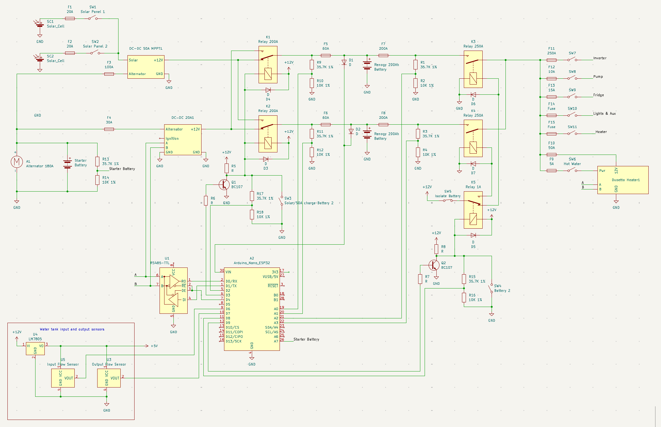
schematic

The power system needs to provide off-grid power for 3 days, which required a 4.8kW or 400Ah battery system.

Since 12V, 400A would require massive fuses, switches and cable etc. I've decided to run the system as 2x isolated batteries, rather than in parallel. This will reduce the need for 400A fuses and switches to 200A fuses ans switches.

The other issue is that the DC-DC battery charger has a maximum output of 50A which would result in a 7-8 hour charge time via the alternator. Being able to independently charge each battery with it's own battery charger solves this problem and also 2x 50A chargers are a lot cheaper than a single 100A charger.

The system is designed so the batteries can never be inadvertently connected in parallel.

There are two modes of operation:

  • Manual
  • Automatic

Manual mode will override any automatic setting and allows the selection of:

  • which battery to use for powering appliances
  • swapping the dc-dc battery chargers. This will allow selection of which battery to charge via Solar Cells/50A DC-DC charger or 20A DC-DC charger.

Automatic mode will select the battery to use for powering appliances. When the battery charge falls below a certain threshold it will swap to the other battery.

Automatic mode will also swap chargers during driving to ensure the optimum charge time for both batteries. When the ignition is off, charging via solar cells will automatically switch to the second battery when the first is fully charged.

Sensors

There are a variety of sensors in use:

  • voltage dividers
  • RS485 which will require some reverse engineering
  • Hall effect devices
  • Bluetooth for the smart batteries and 50A DC-DC

The following devices are monitored for the associated properties using a voltage divider:

  • Starter Battery voltage
  • Battery 1 input voltage (before 60A fuse)
  • Battery 1 output voltage (after 200A fuse)
  • Battery 2 input voltage (before 60A fuse)
  • Battery 2 output voltage (after 200A fuase)
  • Battery 2 charge switch status - to a digital input
  • Battery 2 switch status - to a digital input

The following are monitored via RS485:

  • 20A DC-DC battery charger
  • Duoetto Heater

The following are monitored via hall effect devices:

  • Water input flow
  • Water output flow

The following devices are bluetooth enabled:

  • Battery 1
  • Battery 2
  • 50A DC-DC charger

Schematic design software used is Kicad

Circuit Design

General Design requirements

  • All inputs and outputs of the main management module to be optically isolated to prevent any issues with voltage spikes damaging the module and to also reduce any potential issues with ground loops and noise.

Battery and voltage monitoring

Linear OptoCoupler Design

An IL300 linear opto-coupler is used to monitor the voltage of the following:

  • Starter Battery
  • Battery 1
  • Battery 2
Voltage Divider Design

The typical battery voltage ranges from 10.0V - 14.4V and the maximum input voltage levels are ether 3.3V or 5V depending on the Arduino device used. In order to keep power consumption low large value resistors in the 100k range will be used. But with such large values noise increases (Johnson noise) and the inputs to the ADC on the Arduino or external ADC (MCP3008 or MCP3208) require a low impedance source so a unity gain low pass filter will be required.
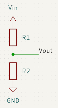
Voltage Divider

Equation for the voltage divider is:

R1 = R2(Vin - Vout)/Vout

Using an input voltage of 15.0V and choosing R2 = 100k Gives:

  • R1 = 357k 1% for a 3.3V output
  • R1 = 200k 1% for a 5V output
Low Pass Filter

A simple 2 pole Butterworth low pass filter will be used. A quick web search shows that a 0.1Hz - 1Hz filter should be used, which sounds reasonable to me. I'll use 1Hz to keep the capacitor value on the lower end.
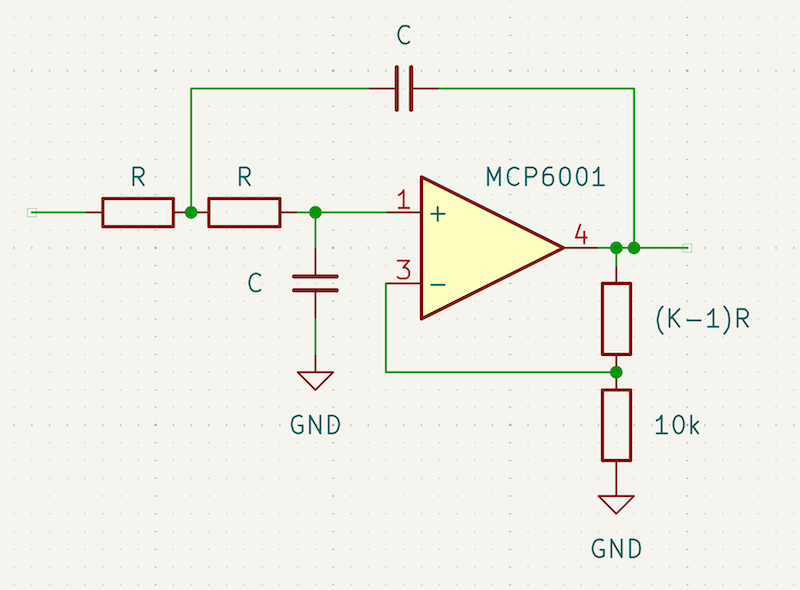
Butterworth Filter

Formula for a low pass filter is:

  • RC = 1/(2*pi*Cn*f)

Cn and K are constants that are used to set various low pass filter types. For a 2 pole Butterworth the values are:

  • Cn = 1
  • K = 1.586

Refer to "The Art of Electronics page 408".

For:

  • f = 1Hz
  • C = 1uF

Gives:

  • R = 154k 1%
  • Rga = (K-1)R = 5k9 1%

TODO

  • add an Oled touch panel
  • ignition switch input

Parts

183
QtyValueFootprintReferences
20100nFCapacitor_SMD:C_0805_2012MetricC2, C4, C16, C19, C20, C21, C22, C23, C24, C25, C26, C27, C28, C31, C32, C47 +4
151uFCapacitor_SMD:C_0603_1608MetricC1, C3, C15, C33, C34, C36, C41, C42, C43, C44, C45, C46, C49, C51, C52
14LTV-817S-TA1-CPackage_SO:SO-4_4.4x3.6mm_P2.54mmU3, U4, U6, U7, U9, U10, U11, U12, U13, U14, U15, U16, U26, U27
1110kResistor_SMD:R_0603_1608MetricR4, R5, R6, R36, R37, R39, R41, R43, R51, R52, R53
810uFCapacitor_SMD:C_1206_3216MetricC5, C6, C7, C8, C9, C10, C12, C13
8150Resistor_SMD:R_0805_2012MetricR11, R12, R20, R23, R25, R26, R29, R30
6150kResistor_SMD:R_0603_1608MetricR45, R46, R47, R48, R49, R50
6C_SmallCapacitor_SMD:C_0603_1608MetricC29, C30, C35, C39, C40, C53
6FDS4685Package_SO:SOIC-8_3.9x4.9mm_P1.27mmQ1, Q2, Q3, Q4, Q5, Q6
6M7Diode_SMD:D_SMAD3, D5, D6, D7, D8, D10
55k6Resistor_SMD:R_0603_1608MetricR40, R42, R44, R57, R58
5LM358DR2GCV_connector:SOIC-8_ONS-LU17, U18, U23, U24, U25
410uFCapacitor_Tantalum_SMD:CP_EIA-3216-18_Kemet-AC17, C18, C37, C38
41N418WDiode_SMD:D_SOD-123D1, D2, D4, D9
447kResistor_SMD:R_0805_2012MetricR13, R24, R27, R28
4680Resistor_SMD:R_0805_2012MetricR14, R15, R19, R21
4MountingHole_PadMountingHole:MountingHole_4.3mm_M4_PadH1, H2, H3, H4
310kPotentiometer_THT:Potentiometer_Bourns_3296W_VerticalR54, R55, R56
31k2Resistor_SMD:R_0603_1608MetricR31, R35, R38
3220kResistor_SMD:R_0603_1608MetricR32, R33, R34
3HCNR200-500EPackage_DIP:SMDIP-8_W11.48mmU19, U20, U21
3TestPointCV_connector:5000TP1, TP2, TP3
21MResistor_SMD:R_0805_2012MetricR10, R22
2931Resistor_SMD:R_0805_2012MetricR16, R18
2AMS1117-3.3/TLV761Package_TO_SOT_SMD:SOT-223-3_TabPin2U5, U22
2MCP16311x-xMNYPackage_DFN_QFN:DFN-8-1EP_3x2mm_P0.5mm_EP1.75x1.45mmU1, U2
2MMBT2222APackage_TO_SOT_SMD:SOT-23Q7, Q8
2PolyfuseFuse:Fuse_1812_4532MetricF1, F2
1120Resistor_SMD:R_0805_2012MetricR17
118uHInductor_SMD:L_Coilcraft_MSS1038-XXXL1
11kResistor_SMD:R_0805_2012MetricR7
1220pFCapacitor_SMD:C_0805_2012MetricC14
1220uFCapacitor_THT:C_Radial_D6.3mm_H11.0mm_P2.50mmC11
127kResistor_SMD:R_0805_2012MetricR8
1330Resistor_SMD:R_0805_2012MetricR9
1330kResistor_SMD:R_0603_1608MetricR1
133uHInductor_SMD:L_Coilcraft_MSS1038-XXXL2
147kResistor_SMD:R_0603_1608MetricR2
168kResistor_SMD:R_0603_1608MetricR3
1Arduino_Nano_ESP32Module:Arduino_NanoA1
1Battery & FuseConnector_Molex:Molex_Mini-Fit_Jr_5566-04A_2x02_P4.20mm_VerticalJ1
1Battery 2Connector_Molex:Molex_Mini-Fit_Jr_5566-02A_2x01_P4.20mm_VerticalJ2
1FansConnector_Molex:Molex_Mini-Fit_Jr_5566-04A_2x02_P4.20mm_VerticalJ6
1G5V-2Relay_THT:Relay_DPDT_Omron_G5V-2K1
1Input Flow SensorConnector_Molex:Molex_Mini-Fit_Jr_5566-04A_2x02_P4.20mm_VerticalJ11
1MAX487EPackage_SO:SOIC-8_3.9x4.9mm_P1.27mmU8
1Output Flow SensorConnector_Molex:Molex_Mini-Fit_Jr_5566-04A_2x02_P4.20mm_VerticalJ10
1Power On/Off SwitchConnector_Molex:Molex_Mini-Fit_Jr_5566-04A_2x02_P4.20mm_VerticalJ4
1RS485Connector_Molex:Molex_Mini-Fit_Jr_5566-02A_2x01_P4.20mm_VerticalJ5
1RelaysConnector_Molex:Molex_Mini-Fit_Jr_5566-04A_2x02_P4.20mm_VerticalJ7
1SW_PushCV_connector:SW_SPST_JLCSW1
1Solar ChargeConnector_Molex:Molex_Mini-Fit_Jr_5566-02A_2x01_P4.20mm_VerticalJ3
1Starter BatteryConnector_Molex:Molex_Mini-Fit_Jr_5566-02A_2x01_P4.20mm_VerticalJ9
1TempConnector_Molex:Molex_Mini-Fit_Jr_5566-04A_2x02_P4.20mm_VerticalJ8

More from akladnig/CamperVan

2
  • 4 layers169.5 × 96 mmCampervan management V2.1, the printed circuit board in 3D

    Campervan management V2.1

    akladnig/CamperVan

    - CamperVan Design and Arduino Circuit Design - Campervan Design Overview - Dashboard App - Electrical System - Sensors - Circuit Design - Battery and voltage monitoring - Voltage Divider Design - Low Pass Filter - TODO

    172 parts
  • 2 layers181.1 × 139.9 mmCampervan management, the printed circuit board in 3D

    Campervan management

    akladnig/CamperVan

    - CamperVan Design and Arduino Circuit Design - Campervan Design Overview - Dashboard App - Electrical System - Sensors - Circuit Design - Battery and voltage monitoring - Voltage Divider Design - Low Pass Filter - TODO

    116 parts

Similar boards

  • 2 layers123.2 × 50.2 mmRp2040 rs485 scale breakout, the printed circuit board in 3D

    Rp2040 rs485 scale breakout

    abzman/modular-i2c-board-set

    boards designed to be used together to create a modular control system

    109 parts1Unlicense
  • 2 layers74 × 38 mmBoop, the printed circuit board in 3D

    Boop

    dekomote/boop

    Power and reset your PC with ESPHome

    27 parts2CC-BY-SA-4.0
  • 2 layers100 × 100 mmUlva controller, the printed circuit board in 3D

    Ulva controller

    ivere27/ulva

    controller board for robotics and agriculture

    106 partsMIT
  • 4 layers159.6 × 130 mmFE UFPR 4 0, the printed circuit board in 3D

    FE UFPR 4 0

    josearistidesbail/FE_UFPR_4_0

    KiCad 10 project for the board that sits between a TI LAUNCHXL-F28379D (runs the FOC firmware) and an Infineon PrimeSTACK 6PS04512E43W39693 inverter driving an EMRAX 208 motor.

    374 parts
  • 2 layers100.5 × 83 mmPicoLogger, the printed circuit board in 3D

    PicoLogger

    WestianPKl/Logger_Dashboard

    A full-stack IoT monitoring platform for collecting, visualizing, and managing environmental sensor data from distributed devices.

    65 parts
  • 2 layers70 × 40 mmHallTapBoard, the printed circuit board in 3D

    HallTapBoard

    ssbingo/samba-solar-track

    Samba Solar Track – Solarnachführung mit Sturmschutz: Handbuch, Platine und Gehäuse für den Nachbau (10,1-Zoll-Version)

    58 parts
  • 2 layers10 × 50.8 mmIN-24V, the printed circuit board in 3D

    IN-24V

    Thierry-oshw/Allumettes

    module 5mm x 34mm de fonction unitaire

    15 partsCERN-OHL-P-2.0

Questions

How big is the Campervan management V2 PCB?

It measures 130 × 150 mm and has 4 copper layers, 1.6 mm thick.

What parts does the Campervan management V2 use?

183 parts, built around the MAX487EPA+, RS485, LM358DR2GH and LTV-817S-TA1-C. The full list of its parts is on this page, with links to each part's symbol and footprint where PCBKit's library has them.

Where can I download the Campervan management V2 KiCad files?

From the akladnig/CamperVan repository on GitHub, at the commit this page was made from: the board is electrical/campervan_management_V2/campervan_management_V2.kicad_pcb and its schematic electrical/camper_van.kicad_sch. PCBKit opens the board in the browser, with nothing to install.

Can I use the Campervan management V2 design in my own project?

Its repository states no licence, so its author keeps all rights: ask akladnig before reusing the design.