
2 layers100 × 99.8 mm

 akita11/StepperDriverUnit1
StepperDriverU is an open-source printed circuit board by akita11, from the akita11/StepperDriverUnit repository on GitHub, published under the MIT licence. It is a 2-layer board of 20.6 × 28 mm with 23 parts on 27 nets, routed with 298 tracks and 34 vias.
It is built around the DRV8825PWP. Its parts include 6 resistors, 5 capacitors, 5 connectors, 1 IC and 1 diode.

ステッピングモータをGrove端子からの方向・パルスのみで制御できるUNITです。ドライバICはよく使われるDRV8825の互換IC(HR8255)を使用しており、マイクロステップ駆動も可能です。またイネーブル・リセットは別の端子から与えることもできます。

Grove端子のピン配置(基板裏面にシルク表記あり): STP/DIR/+5V/GND
UIFlowでの使用例(以下)を参考にしてください。(Core2のPortAに接続した場合。STEP=GPIO33, DIR=GPIO32)

半固定抵抗(RV1)でモータの駆動電流を設定てきます。また動作異常時にはD1(Fault)が点灯します。


基板裏面の4つのソルダージャンパで、モータの駆動方法を設定できます。詳細はHR8825(またはDRV8825)のデータシートを参照してください。

| M0 | M1 | M2 | マイクロステップ |
|---|---|---|---|
| x | x | x | フルステップ |
| o | x | x | 1/2ステップ |
| x | o | x | 1/4ステップ |
| o | o | x | 8 microステップ |
| x | x | o | 16 microステップ |
| o | x | o | 32 microステップ |
| x | o | o | 32 microステップ |
| o | o | o | 32 microステップ |
Junichi Akita (akita@ifdl.jp / @akita11)
| Qty | Value | Footprint | References |
|---|---|---|---|
| 3 | Jumper_2_Open | Jumper:SolderJumper-2_P1.3mm_Open_Pad1.0x1.5mm | JP1, JP2, JP3 |
| 2 | 0.1u | Capacitor_SMD:C_0603_1608Metric | C2, C3 |
| 2 | 0.2 | Resistor_SMD:R_0805_2012Metric | R2, R6 |
| 2 | CON_GROVE | akita:CON_GROVE_H | CN1, CN2 |
| 2 | Conn_01x02 | Connector_PinSocket_2.54mm:PinSocket_1x02_P2.54mm_Vertical | J2, J3 |
| 1 | 0.47u | Capacitor_SMD:C_0603_1608Metric | C4 |
| 1 | 1.5k | Resistor_SMD:R_0603_1608Metric | R5 |
| 1 | 10k | Resistor_SMD:R_0603_1608Metric | R3 |
| 1 | 10u | Capacitor_SMD:C_1206_3216Metric | C5 |
| 1 | 1k | Potentiometer_SMD:Potentiometer_Bourns_TC33X_Vertical | RV1 |
| 1 | 1k | Resistor_SMD:R_0603_1608Metric | R1 |
| 1 | 1u | Capacitor_SMD:C_0603_1608Metric | C1 |
| 1 | Conn_01x06 | Connector_PinSocket_2.54mm:PinSocket_1x06_P2.54mm_Vertical | J1 |
| 1 | DRV8825 | Package_SO:HTSSOP-28-1EP_4.4x9.7mm_P0.65mm_EP2.85x5.4mm_ThermalVias | U1 |
| 1 | LED | LED_SMD:LED_0603_1608Metric | D1 |
| 1 | NC | Resistor_SMD:R_0603_1608Metric | R4 |
| 1 | SolderJumper_3_Open | Jumper:SolderJumper-3_P1.3mm_Open_Pad1.0x1.5mm | JP4 |
It measures 20.6 × 28 mm and has 2 copper layers, 1.6 mm thick.
23 parts, built around the DRV8825PWP. The full list of its parts is on this page, with links to each part's symbol and footprint where PCBKit's library has them.
From the akita11/StepperDriverUnit repository on GitHub, at the commit this page was made from: the board is StepperDriverU.kicad_pcb and its schematic StepperDriverU.kicad_sch. PCBKit opens the board in the browser, with nothing to install.
Its repository publishes it under the MIT licence: you may reuse it on that licence's terms (keep the author's notice, and for a copyleft licence share your changes alike).

mathias31415/diy_robotics
Gripper, PCBs and ROS2 software for Six-Axis Robot Arm WE-R2.4 from LoboCNC

o7-machinehum/Hydroponic
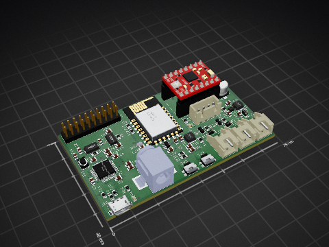
Please find the electronics files in the ee folder, all pcb design is done with the open source software KiCad. Is uses an STM32 as the main controller, and an ST L6470 moter driver for the stepper motor.

eli3162/diw_printer
Direct ink Writing(DIW) is a technology that enables 3d printers to print many gels, solvents, and other liquids instead of normal plastic filaments.


