2 layers95 × 95 mm

 akaFunk/EDice
A very cheap electronic dice used for soldering exercises
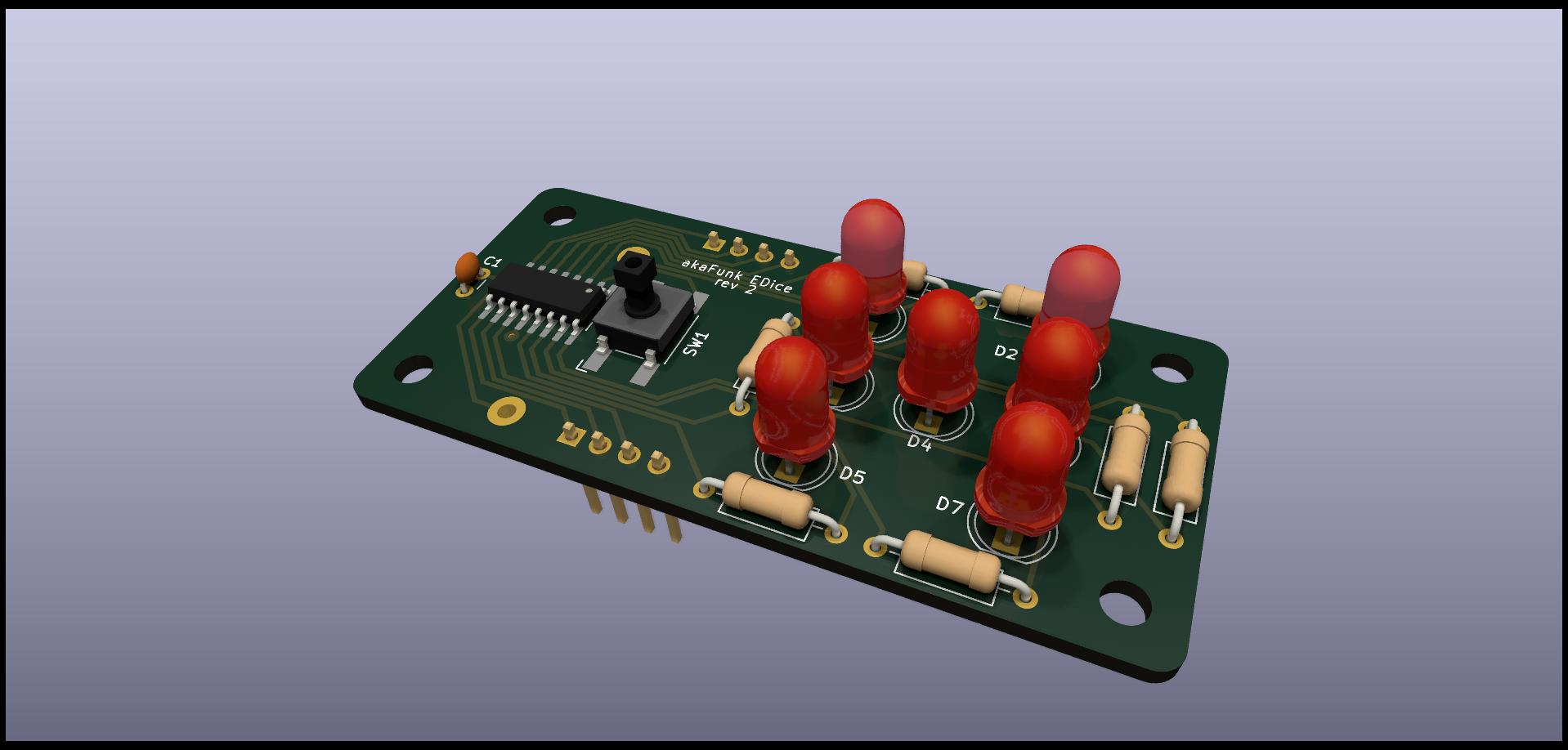
EDice is an open-source printed circuit board by akaFunk, from the akaFunk/EDice repository on GitHub. It is a 2-layer board of 65 × 30 mm with 24 parts on 23 nets, routed with 122 tracks and 3 vias.
It is built around the PFS154-S16, BS-02-A1AJ010 and K2-1102DP-J4SW-04. Its parts include 7 resistors, 7 diodes, 2 connectors, 1 capacitor and 1 IC.


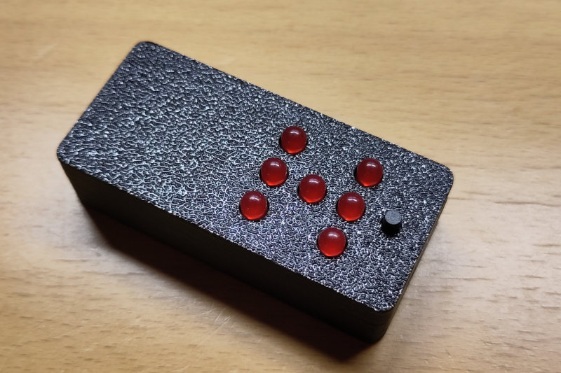
The EDice is a small and fairly simple device that simulates a dice by using some LEDs, resistors and a microcontroller. The controller used is a Padauk PFS154-S16, which is an extremly cheap 8 bit microcontroller. It can be purchased from LCSC and other sources for less than 10 Euro-Cents.
The EDice is used as a simple soldering exercise. Therefore it has a combination of (relatively large) SMD and through-hole parts.
It is powered by a single CR2032 3V coin cell, which is on the back of the PCB. The holder we use is the BS-02-A1AJ010, which can also be purchased from LCSC for less than 5 Euro-Cents a pop.
Together with the PCB and a few other components, the whole cost is approximately 1€ in quantaties of about 100. This includes everything except the prommer (PCB, components, 3D case, shipping), which makes it ideal for a give-away item.
Building is pretty straight forward. A few things to note:
We used LCSC for component sourcing. Here is our list:
There are probably cheaper things out there, we did not look too hard into it.
After installing the required software listed below, connect the EDice to the prommer (WITHOUT A BATTERY!) and run:
make clean program run
With the run command, the prommer will power the EDice and it should work right away.
To program the Padauk microcontroller you need a Free-PDK prommer: https://free-pdk.github.io/
You also need to install the SDCC compiler (version 4.4.0 or higher) which you can install through your packet manager.
Microsoft being Microsoft, it is a little more tricky to run make on Windows than it is on Linux. However, you san still do it - with a few extra steps. To run make and the programmer on Windows, you will need to:
choco install make in an admin privileged command prompt.easypdkprog to your PATH manually.After completing the installation, you can now compile and upload your code to the EDice by opening Git Bash (or another Linux Shell) in the directory containing the Makefile and running the commands listed in the section above.
Hold the button for a few seconds to roll the dice. A short press or waiting for ~20 seconds will put it in power-down mode, consuming less than 0.1µA. The battery should last for years.
Hers is a short breakdown of the cost for 100 pcs:
The total cost is then 99€ for 100 pcs.
This does not include the cost for the prommer, which are an additional ~25€.
The PCB and the images are licensed under CC-BY 4.0, the source code is under GPL v2.
For the PCB we used the KiCad symbols made by the free-pdk project: https://github.com/free-pdk/pdk-kicad-symbols/tree/master. This library is licensed under the CC-BY 4.0.
For the software the pdk-includes (GPL v2) https://github.com/free-pdk/pdk-includes and the easy-pdk-includes (GPL v2) https://github.com/free-pdk/easy-pdk-includes are used.
| Qty | Value | Footprint | References |
|---|---|---|---|
| 7 | 1k | Resistor_THT:R_Axial_DIN0207_L6.3mm_D2.5mm_P10.16mm_Horizontal | R1, R2, R3, R4, R5, R6, R7 |
| 7 | LED | LED_THT:LED_D5.0mm | D1, D2, D3, D4, D5, D6, D7 |
| 4 | MountingHole | MountingHole:MountingHole_3.2mm_M3 | H1, H2, H3, H4 |
| 2 | Conn_01x04 | Connector_PinHeader_2.54mm:PinHeader_1x04_P2.54mm_Vertical | J2, J3 |
| 1 | 100n | Capacitor_THT:C_Disc_D3.0mm_W1.6mm_P2.50mm | C1 |
| 1 | Battery_Cell | EDice:BS-02-A1AJ010 | BT1 |
| 1 | PFS154-S16 | Package_SO:SOIC-16_3.9x9.9mm_P1.27mm | U1 |
| 1 | SW_Push | EDice:K2-1102SP-J4SC-04 | SW1 |
It measures 65 × 30 mm and has 2 copper layers, 1.6 mm thick.
24 parts, built around the PFS154-S16, BS-02-A1AJ010 and K2-1102DP-J4SW-04. The full list of its parts is on this page, with links to each part's symbol and footprint where PCBKit's library has them.
From the akaFunk/EDice repository on GitHub, at the commit this page was made from: the board is PCB/EDice.kicad_pcb and its schematic PCB/EDice.kicad_sch. PCBKit opens the board in the browser, with nothing to install.
Its repository states no licence, so its author keeps all rights: ask akaFunk before reusing the design.

serisman/pdk-digital-clock
A 4-digit 7-segment digital clock, based on the inexpensive Padauk microcontrollers

hackwinkel/39C3LEDbadge
hardware design files and firmware for an electronic name tag created for 39C3


bsidestlv/bsidestlv-2026-badge
Everything for the BSidesTLV 2026 badge: two KiCad boards, the RP2040 firmware that runs on it, and the online puzzle challenge — Alice in AI Land — that the badge is used to play.


PHS-SMCS/Falconia-Beacon
Falconia Beacon is an ATTINY816-based, CR2032-powered LED beacon board used to make the Falconia rover visible to the SMCS Pi-in-the-sky satellite.