2 layers280 × 202.8 mm
CoreS3 ILDA RevA
TakuroFukamizu/cores3-ilda
まず ハードウェアREADME を読んでください。KiCad 10で hardware/rev-a/kicad/CoreS3ILDARevA.kicadpro を開きます。ライブラリはプロジェクト相対参照で同梱しています。
168 parts

 aichi-steiner/sequencer8x3ch
コンピューター教育実習用シーケンサ
Sequencer8x3ch is an open-source printed circuit board by aichi-steiner, from the aichi-steiner/sequencer8x3ch repository on GitHub, published under the CERN-OHL-P-2.0 licence. It is a 2-layer board of 99.1 × 99.1 mm with 161 parts on 107 nets, routed with 1,005 tracks and 81 vias.
It is built around the 74HC595, NE555D and NJM2845DL1-05-TE1, with the 1N4148W and HFD27/005-S among its other parts. Its parts include 47 diodes, 44 resistors, 19 capacitors, 9 switches and 7 transistors.


Computer 学習教材の補助として、program された 8bit を順次出力できる sequencer。 横浜シュタイナー学園 佐藤氏設計の回路を一部改良したもの。
Relay をつかって作成した加算器に対して、連続してデータを入力していくことで、computer の program 動作を理解してもらうために利用する。
基板設計は CERN Open Hardware Licence Version 2 - Permissive に従って自由に再配布・改変して構わないが、無保証である。
74HC595 (shift-register logic) を使って、入力された bit を clock 信号に応じて順次送っていくという動作をする。
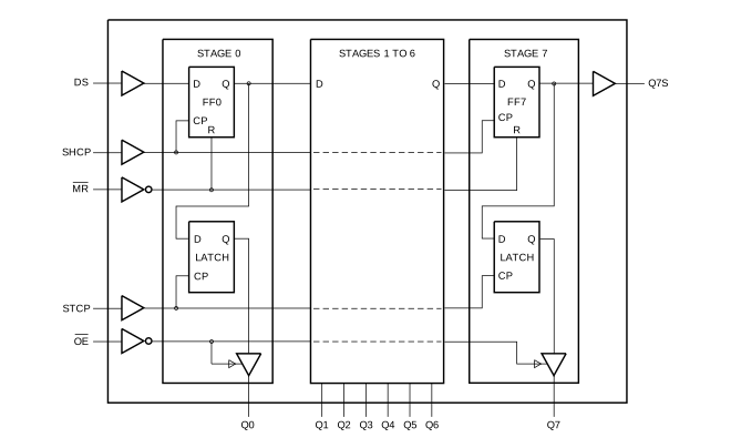
(Nexperia 74HC595 より引用)
SHCP に入力の立ち上りタイミングで FF0〜FF1 の shift register が 1つずつ送られていく。
STCP に入力の立ち上りタイミングで shift register の状態が Q0〜Q7 へ出力されるという動作をする。
SHCP と STCP に同じ信号をいれると、shift 前の状態が Q0〜Q7 へ出力され、内部状態と出力が 1 cycle ずれることになる。
最終段(Q7) の出力を relay で外部出力として取り出す。
ボタンを押したときに SHCP が立ち上り、遅延回路で約8ms 遅れて STCP を H→L→H とすることで、shift 後の状態を LED 出力に反映する。
Timer IC 555 を使った簡易発振器を使って、ボタンを押す代わりに連続動作をできるようにする。
また、Q0 の入力を switch と Q7 の OR とすることで、繰り返しの連続動作する。
555 timer は抵抗と capacitor の容量で発振周波数を設定する。以下のように設計。
2台の sequencer をつなげて利用できるように、片方から clock を出力、もう一方へ clock 入力できるようにしておく。
1台目の 3bit 目が carry (H→L) したときに clock を出力するようにすることで、2台あわせて 0から63 まで 6bit 分を順に数えることができるようになる。 回路として、3bit 目のたち下がり edge で、one shot pulse を出す回路を組むことで実現。
Regurator IC 7805 を使って回路用に安定した 5V を生成する。 これにより電源は 5V〜15V 程度の範囲で動作可能。
各LEDは 470Ω 抵抗を介して、5V logic 出力で直接駆動。
74HC595 は各 port ごとに ±35mA, 全 port 合計で 70mA が absolute max. であるので、合計のほうで余裕をみて LED 駆動電流は全点灯時 6mA × 8 LED = 48mA 狙いで設計。 赤色、緑色LED は Vf ≒ 2.1V なので、5V 電源であれば (5V-2.1V)/6mA ≒ 480Ω → 入手性のよい E6 系列の 470Ω を電流制限抵抗とする。
また、LEDは high level 側で点灯させる。low で LED on (流し込み) で使うことが多いが、74HC595 は high, low 対称に 35mA 流せること、reset 後が low 出力になることから、high 側駆動とする。
最終段は relay (HFD27/005-S) を駆動。5V/125Ω = 40mA 入るので、Tr で buffering する。 安価な Rohm の抵抗入り Tr 利用。
ボタン入力の chattering として、LPF → schmitt trigger を介して、74HC595 の SHCP へ入力。
発振器で利用する timer IC 555 は schmitt trigger inverter としての動作も可能なため、これを利用。
何枚かまとめて作りたいため、PCB を製作。 Open source の 基板 CAD である KiCad 10 を使用。
秋月電子で購入可能な部品で構成。
| 回路図記号 | 型番 | 個数 | 秋月部品番号 |
|---|---|---|---|
| U1-3 | TC74HC595AF | 3 | 110077 |
| U4,U5 | NE555D | 2 | 116210 |
| U6 | NJM2845DL1-05 | 1 | 111298 |
| K1-3 | HFD27/005-S or 941H-2C-5D | 3 | 130122 or 101229 |
| D1-9 | 1N4148W | 9 | 116985 |
| D11-19 | 1N4007 | 9 | 108327 |
| Q1-Q7 | DTC123JU3 | 7 | g131814 |
| LED ** | LED 3mm | 29 | 111577, 111637 など |
| C1-16 | 1uF 1608 | 15 | 130397 |
| C20 | 22uF | 1 | 117899 |
| R10-45 | 470Ω 1608 | 34 | 130349 |
| R49 | 3.3kΩ 1608 (470Ωで代用も可) | 1 | ( 114661 ) |
| R50-55 | 10kΩ 1608 | 6 | 130355 |
| R61-63 | 10Ω 1W | 3 | 107956 |
| VR1 | 0-100kΩ TSR-3386T-EY5-104TR | 1 | 108014 |
| SW1 - SW4 | 基板用小型3Pトグルスイッチ | 4 | 112406 など |
| SW5,6 | タクトスイッチ | 2 | 117166 など |
| CN1 | XHオス 2pin | 1 | 112247 |
| - | DCジャック - XH | 1 | 115798 |
| - | 電池端子 - XH | 1 | 112245 |
| CN3,4 | XHオス 3 pin | 2 | 112248 |
| - | XHメス 3 pin | 2 | 112256 |
| - | XH contact付きケーブル | 1 pack | 131309 |
| - | (XH contact, ケーブル自作の場合) | 1 pack | 112264 |
Capacitor, 抵抗は入手性のよい E6 系列から選択。 Diode, transistor は汎用性の高い品種を選択(安価だし)。
IC について、555 timer は汎用性が高く様々な回路で利用されており、今後も入手は容易だろう。 7400 の標準 logic は利用が減っており今後入手性は悪化の方向。 その中で、74HC595については LED matrix の駆動という標準 logic 以外の用途でも利用されているため、これは当面入手は可能だろう。 他の 7400 series は今後の入手性は不透明になっていくので利用しない方向で設計した。
Relayについても今後の入手性は未知数ではあるが、秋月で2種類互換品のある品種なので、割と入手性はよいと想定。(Omron G6A footprint互換)
| Qty | Value | Footprint | References |
|---|---|---|---|
| 34 | 470 | Resistor_SMD:R_0603_1608Metric_Pad0.98x0.95mm_HandSolder | R10, R11, R12, R13, R14, R15, R16, R17, R18, R20, R21, R22, R23, R24, R25, R26 +18 |
| 29 | LED | LED_THT:LED_D3.0mm | LED10, LED11, LED12, LED13, LED14, LED15, LED16, LED17, LED18, LED20, LED21, LED22, LED23, LED24, LED25, LED26 +13 |
| 17 | TestPoint | TestPoint:TestPoint_Bridge_Pitch2.54mm_Drill1.3mm | TP1, TP2, TP11, TP12, TP13, TP15, TP16, TP21, TP22, TP23, TP25, TP26, TP31, TP32, TP33, TP35 +1 |
| 15 | 1u | Capacitor_SMD:C_0603_1608Metric_Pad1.08x0.95mm_HandSolder | C1, C2, C3, C4, C5, C6, C7, C8, C9, C11, C12, C13, C14, C15, C16 |
| 9 | 1N4007 | Diode_THT:D_DO-35_SOD27_P7.62mm_Horizontal | D11, D12, D13, D14, D15, D16, D17, D18, D19 |
| 9 | 1N4148W | Diode_SMD:D_SOD-123 | D1, D2, D3, D4, D5, D6, D7, D8, D9 |
| 7 | DTC123JU3 | Package_TO_SOT_SMD:SOT-323_SC-70 | Q1, Q2, Q3, Q4, Q5, Q6, Q7 |
| 6 | 10k | Resistor_SMD:R_0603_1608Metric_Pad0.98x0.95mm_HandSolder | R50, R51, R52, R53, R54, R55 |
| 4 | SW_SPDT | Connector_PinHeader_2.54mm:PinHeader_1x03_P2.54mm_Vertical | SW1, SW2, SW3, SW4 |
| 3 | 10 | Resistor_THT:R_Axial_DIN0207_L6.3mm_D2.5mm_P2.54mm_Vertical | R61, R62, R63 |
| 3 | 74HC595 | Package_SO:SOIC-16W_5.3x10.2mm_P1.27mm | U1, U2, U3 |
| 3 | HFD27/005-S | Relay_THT:Relay_DPDT_Omron_G6A | K1, K2, K3 |
| 2 | 10n | Capacitor_SMD:C_0603_1608Metric_Pad1.08x0.95mm_HandSolder | C30, C31 |
| 2 | JST XH2 | Connector_JST:JST_XH_B2B-XH-A_1x02_P2.50mm_Vertical | CN1, CN2 |
| 2 | JST XH3 | Connector_JST:JST_XH_B3B-XH-A_1x03_P2.50mm_Vertical | CN3, CN4 |
| 2 | Jumper_2_Small_Bridged | Jumper:SolderJumper-2_P1.3mm_Bridged2Bar_RoundedPad1.0x1.5mm | JP1, JP2 |
| 2 | NE555D | Package_SO:SOIC-8_3.9x4.9mm_P1.27mm | U4, U5 |
| 2 | SW_Push | Button_Switch_THT:SW_PUSH_6mm | SW5, SW6 |
| 1 | 0-100k | Potentiometer_THT:Potentiometer_Bourns_3386W_Horizontal | VR1 |
| 1 | 2.2k | Resistor_SMD:R_0603_1608Metric_Pad0.98x0.95mm_HandSolder | R49 |
| 1 | 22uF | Capacitor_THT:CP_Radial_D5.0mm_P2.00mm | C20 |
| 1 | 47uF | Capacitor_THT:CP_Radial_D5.0mm_P2.00mm | C21 |
| 1 | Logo_Open_Hardware_Small | Symbol:OSHW-Symbol_13.4x12mm_SilkScreen | SYM1 |
| 1 | NJM2845DL1-05 | Package_TO_SOT_SMD:TO-252-2 | U6 |
The 157 most common of 161 parts.
It measures 99.1 × 99.1 mm and has 2 copper layers, 1.6 mm thick.
161 parts, built around the 74HC595, NE555D, NJM2845DL1-05-TE1 and 1N4148W. The full list of its parts is on this page, with links to each part's symbol and footprint where PCBKit's library has them.
From the aichi-steiner/sequencer8x3ch repository on GitHub, at the commit this page was made from: the board is sequencer8x3ch.kicad_pcb and its schematic sequencer8x3ch.kicad_sch. PCBKit opens the board in the browser, with nothing to install.
Its repository publishes it under the CERN-OHL-P-2.0 licence: you may reuse it on that licence's terms (keep the author's notice, and for a copyleft licence share your changes alike).
TakuroFukamizu/cores3-ilda
まず ハードウェアREADME を読んでください。KiCad 10で hardware/rev-a/kicad/CoreS3ILDARevA.kicadpro を開きます。ライブラリはプロジェクト相対参照で同梱しています。


CUERT-dev/ElectricalRndD_TeamDev
production : gerbers for production and bom bom : html interactive bom LIB : component library used Doc : 3d model , images , schematic (pdf) , etc s

ibScale/ibScaleSeqRails
Sequential feeder rails with power protection for the LumenPNP
