
2 layers151.3 × 50.8 mm

 agaelema/Precision-Voltage-Reference7
A simple and efficient instrumentation project of a Precision Voltage Reference. The idea of this project appeared with my passion by the instrumentation and my need of some reference to calibrate my projects involving…
Ref fixa v02 is an open-source printed circuit board by agaelema, from the agaelema/Precision-Voltage-Reference repository on GitHub, published under the MIT licence. It is a 2-layer board of 84 × 69.5 mm with 69 parts on 46 nets, routed with 545 tracks and 15 vias.
It is built around the INA2133UA, LM358 and LM317AT, with the LM337T and REF102BP among its other parts. Its parts include 20 resistors, 6 ICs, 5 capacitors and 1 diode.


A simple and efficient instrumentation project of a Precision Voltage Reference. The idea of this project appeared with my passion by the instrumentation and my need of some reference to calibrate my projects involving energy measurement.
Searching for similar projects I encountered some videos from the Youtube channel "Scullcom Hobby Electronics". This two videos was the kick for my project.
The project is based in the TI REF102, an 10 V precision voltage reference with maximum tolerance of 0,025% (0.0025 V) in the better model.
Other 4 outputs are derived from the 10 V output, making available 10 V, 5V, 2,50V, 1,125 V and 0,625 V. This values are obtained using the Precision Difference Amplifier INA2133
The original idea is to be a simple project with components easily found in the market.
The project is powered by a common 5V power bank, and the output of the power bank is applied to a DC/DC step up to 20 V. With one LM317 and one LM337 we generates the positive supply for the REF102 and negative voltage to compensate some offset in the INAs.
The output is referenced to a Virtual ground, not the GND from the power bank.

Using the INA2133 is possible to implement a 1/2 divider with great precision. At the same time the outputs are buffered between the stages.
To compensate some possible input offset in the stages, was implements simple circuits to externally compensate the offset. This circuit inject some voltage in the Ref pin of the INA.
The ideia of divider:

The project was developed using Kicad. The complet schematic is presented bellow.


The assembled board.

The results without calibration (default value), calibrating just the REF102 output and calibrating each output individually.
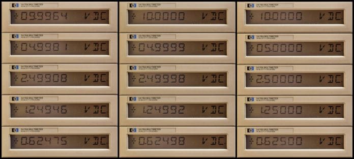
There is a serie of 4 articles talking about this project.
This project is provided 'as is' with no explicit or implied warranties in respect of its properties, including, but not limited to, correctness and/or fitness for purpose.
| Qty | Value | Footprint | References |
|---|---|---|---|
| 9 | CONN_01X01 | My_Edited:PINTST-2.4-1.0mm | 0.625V, 1.25V, 2.5V, 5V, 10V, Bat_in, VCC_reg-, VCC_reg+, Vgnd |
| 8 | 10 | My_Edited:Resistor_Horizontal_RM10mm-2.3-0.85mm | R9, R10, R12, R13, R17, R18, R19, R20 |
| 7 | JUMPER | My_Edited:Pin_Header_Straight_1x02-2,1-1,2mm | JP1, JP2, JP3, JP4, JP5, JP6, JP7 |
| 5 | 1uF | My_Edited:C_Radial_D5_L6_P2.5-1.6mm | C_U4, C_U5, C_U6, C5, CF1 |
| 4 | 1.2k | My_Edited:Resistor_Horizontal_RM10mm-2.3-0.85mm | R11, R14, R15, R16 |
| 4 | 100k | My_Edited:Potentiometer-pinlinear-2.1-0.85mm | RV2, RV3, RV4, RV5 |
| 4 | 100nF | My_Edited:C_Disc_D3_P2.5-1.8-0.85mm | C2, C3, C4, CF3 |
| 4 | 10uF | My_Edited:C_Radial_D5_L6_P2.5-1.6mm | C_U2, C_U3, C1, CF2 |
| 4 | 1pin | Connect:1pin | , , , |
| 2 | 470 | My_Edited:Resistor_Horizontal_RM10mm-2.3-0.85mm | R4, R6 |
| 2 | INA2133UA | My_Edited:SOIC-14_N-0.75mm | U5, U6 |
| 1 | 100 | My_Edited:Resistor_Horizontal_RM10mm-2.3-0.85mm | R7 |
| 1 | 100k | My_Edited:Resistor_Horizontal_RM10mm-2.3-0.85mm | R3 |
| 1 | 100nF | Capacitors_ThroughHole:C_Rect_L4_W2.5_P2.5 | C6 |
| 1 | 10k | My_Edited:Resistor_Horizontal_RM10mm-2.3-0.85mm | R1 |
| 1 | 18V-22V | My_Edited:bornier2-edit | DC/DC_in |
| 1 | 1M | My_Edited:Resistor_Horizontal_RM10mm-2.3-0.85mm | R8 |
| 1 | 1N4148 | My_Edited:Diode_DO-35_SOD27_Horizontal_RM10-2.1mm | D1 |
| 1 | 20k | My_Edited:Potentiometer-pinlinear-2.1-0.85mm | RV1 |
| 1 | 22 | My_Edited:Resistor_Horizontal_RM10mm-2.3-0.85mm | RF1 |
| 1 | 2k2 | My_Edited:Resistor_Horizontal_RM10mm-2.3-0.85mm | R2 |
| 1 | 3k9 | My_Edited:Resistor_Horizontal_RM10mm-2.3-0.85mm | R5 |
| 1 | JUMPER | Pin_Headers:Pin_Header_Straight_1x02 | JP8 |
| 1 | LM317AT | My_Edited:TO-220-3d | U2 |
| 1 | LM337T | My_Edited:TO-220-3d | U3 |
| 1 | LM358 | My_Edited:PDIP-8-3d-2.1-0.85mm | U1 |
| 1 | REF102BP | My_Edited:PDIP-8-3d-2.1-0.85mm | U4 |
It measures 84 × 69.5 mm and has 2 copper layers, 1.6 mm thick.
69 parts, built around the INA2133UA, LM358, LM317AT and LM337T. The full list of its parts is on this page, with links to each part's symbol and footprint where PCBKit's library has them.
From the agaelema/Precision-Voltage-Reference repository on GitHub, at the commit this page was made from: the board is v02 - artigo/Ref_fixa_v02.kicad_pcb. PCBKit opens the board in the browser, with nothing to install.
Its repository publishes it under the MIT licence: you may reuse it on that licence's terms (keep the author's notice, and for a copyleft licence share your changes alike).

N4ch0VS/fuente-lineal-regulable
Diseño en KiCad de una fuente de alimentación lineal regulable, con esquemático, PCB y lista de componentes, pensada para obtener un voltaje de salida ajustable de forma estable.


