SDR and IoT Network for CubeSat Data Transmission: Design and Implementation
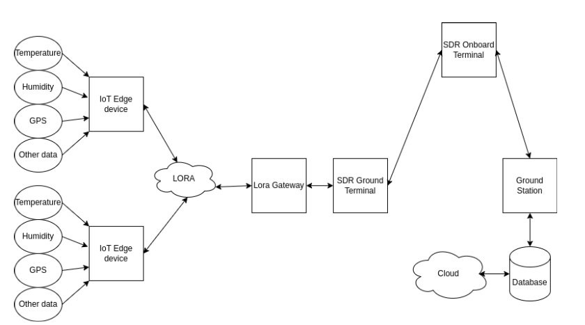
The flow diagram above shows data flow from the IoT Edge devices, through the CubeSat to a ground terminal.
1. Introduction.
This repository contains the design and implementation strategy for an innovative Software-Defined Radio (SDR) and Internet of Things (IoT) network that revolutionizes data collection and transmission for CubeSat missions. By integrating IoT edge devices, LoRa technology and SDR systems based on STM32 microcontrollers, we create a flexible, scalable, and efficient data pipeline from ground-based sensors to space-based CubeSats, and back to Earth-based cloud systems.
2. System Architecture Overview
Our system consists of the following key components:
- IoT Edge Devices: Collect environmental data (temperature, humidity, GPS, etc.)
- LoRa Network: Facilitates long-range, low-power communication between edge devices and the gateway
- LoRa Gateway: Aggregates data from multiple IoT devices
- SDR Ground Terminal: Interfaces between the LoRa Gateway and the CubeSat
- CubeSat Onboard SDR Terminal: Receives and processes data from the ground SDR terminal
- Ground Station: Receives data from the CubeSat for cloud storage and further analysis
Our key area of focus will be the IoT edge devices, LoRa Network and the SDR components to relay IoT data. A link budget will be done, and this will serve as the guide to the above architecture and design. This is separate from the CubeSat onboard communication system.
3. Design Considerations
3.1. IoT Edge Devices
Requirements
- Low power consumption with support for battery power and solar charging
- Highly portable with a minimal physical footprint
- Long-range, half-duplex LoRa communication capabilities
- Integration of various sensors (temperature, humidity, GPS, etc.) via standard interfaces
- Ability to be upgraded with additional sensors and hardware (highly scalable)
- Over-the-air (OTA) firmware update capabilities
- User interface for configuration, log viewing and settings
Specifications
- Use low-power STM32L4 series or ESP32 microcontrollers for extended battery life
- 3.3V power supply and logic level
- Integrate SX1278 LoRa transceiver module for long-range communication at 433MHz
- Support LoRa network features like Adaptive Data Range (ADR) and encryption
- Provide enough sensor interfaces (I2C, SPI, UART) to connect a variety of environmental sensors
- Design for a modular, upgradable hardware architecture
- Implement OTA firmware update mechanisms for remote device management
- Include a simple web-based or serial interface for configuration, monitoring, and debugging
Component List (Breadboard)
- ESP32 S3 Microcontroller
- DHT sensor
- GPS module
- Atmospheric pressure sensor
- Air quality sensors
- 3.7V 18650 Lithium Ion Battery
- TP4056 Lithium Ion Battery Charger
- Battery holder
- SX1278/SX1276 433MHz LoRa module
- Jumper cables: M-M, M-F, F-F
- SD card module 3.3V, with an 8GB SD card
- Solar panels: 5.5V capacity
Final product
The final product should be a system on a PCB. Key sensors will be built in with available ports for expansion i.e via I2C, UART or SPI.
3.2. LoRa Network
- Frequency selection is based on regional regulations (e.g., 868MHz for Africa)
- Adaptive Data Rate (ADR) to optimize power consumption and range
- Encryption to ensure data security and privacy
3.3. LoRa Gateway with Raspberry Pi
- Raspberry Pi for Multi-core Processing
- Multi-channel capability: Supports multiple LoRa channels (typically 8-16 channels) to manage numerous IoT devices simultaneously, ensuring robust and scalable communication
- Ethernet/Wi-Fi Connectivity for Backhaul: Offers both Ethernet and wi-Fi Connectivity options, enabling reliable backhaul to the SDR Ground Terminal, or other network infrastructures
- Edge Computing capabilities: Equipped with edge computing capabilities for initial data processing and aggregation, reducing latency and optimizing data flow before transmission to the SDR.
- Flexible Deployment: Supports various deployment scenarios, including remote locations, with options for power via mains electricity, battery packs, or solar panels.
3.4. SDR Ground Terminal
- High-performance STM32H7 series microcontroller for robust signal processing capabilities
- Dedicated RF front-end to cover potential satellite frequencies
- Custom SDR software stack optimized for STM32 architecture
- Ensure conformity to the link budget
3.5. CubeSat Onboard SDR Terminal
- Space-grade STM32H7 series microcontroller for reliability in the space environment
- Optimized for low power consumption to meet CubeSat energy constraints
- Reconfigurable firmware to adapt to various communication protocols and frequencies.
- Ensure conformity to the link budget, and little to no interference with other onboard systems.
3.6. Ground Station
- A large aperture antenna system for reliable space-to-ground communication
- Secure interface for cloud storage and processing systems.
4. Implementation Strategy
4.1. Phase 1: Terrestrial IoT Network
- Deploy IoT edge devices with STM32L4 or ESP32 MCUs, and the LoRa Gateway with the Raspberry Pi
- Develop and test LoRa communication protocols and data formats
- Implement initial data processing algorithms at the gateway level
4.2. Phase 2: SDR Integration
- Design of the link budget
- Set up the SDR Ground Terminal using STM32H7 and develop a custon SDR software stack
- Implement and test LoRa to SDR interface protocols
- Simulate space-to-ground communication links using STM32-based SDR hardware
4.3. Phase 3: CubeSat SDR Development
- Design and prototype the CubeSat Onboard SDR Terminal with a space-grade STM32H7 MCU
- Develop firmware configurations for various communication modes
- Conduct extensive testing in simulated space environments (thermal, radiation, vacuum)
4.4. Phase 4: Ground Station and Cloud Integration
- Set up the Ground Station infrastructure and develop control software
- Implement secure data pipelines for Ground Station to cloud storage
- Develop a web-based dashboard for data visualization and analysis
4.5. Phase 5: System Integration and Testing
- Integrate all the STM32-based components in a full system test environment
- Conduct end-to-end communication tests, simulating orbital scenarios
- Optimize system performance, focusing on data throughput and power efficiency
5. Key Innovations and Benefits
- Microcontroller SDR Architecture: Allows for efficient, low-power signal processing and communication, with the flexibility to adapt to various protocols and frequencies
- Scalable IoT Integration: Enables seamless expansion of the sensor network without significant infrastructure changes
- Energy Efficiency: The STM32's low-power modes and optimized protocols minimize power consumption across the system
- Real-time Data Processing: Edge computing with STM32/ESP32 reduces latency and bandwidth requirements.
- Cost-Effective: The utilization of widely available STM32/ESP32 microcontrollers reduces overall system cost and development time
6. Conclusion.
This innovative microcontroller-based SDR and IoT network design offers a robust, flexible, and cost-effective solution for CubeSat-based data collection and transmission. By leveraging the versatility and efficiency of STM32 and ESP32 microcontrollers across both terrestrial and space segments, we create a system that not only meets current needs, but is also adaptable to future requirements and mission profiles.


