4 layers99 × 53.3 mm
PSLab
fossasia/pslab-hardware
PSLab Hardware Design and Schematics https://pslab.io
199 parts1.7kApache-2.0

 adlwar137/Keyboard
A from-the-ground-up keyboard
Keyboard PCB is an open-source printed circuit board by adlwar137, from the adlwar137/Keyboard repository on GitHub. It is a 2-layer board of 261 × 101.9 mm with 147 parts on 135 nets, routed with 1,023 tracks and 143 vias.
It is built around the AMS1117-3.3 and SP0503BAHTG. Its parts include 47 diodes, 44 switches, 22 capacitors, 10 resistors and 7 connectors. It belongs with the keyboards and input boards and the STM32 boards of this library.


A custom mechanical keyboard deisgned and built from the ground up
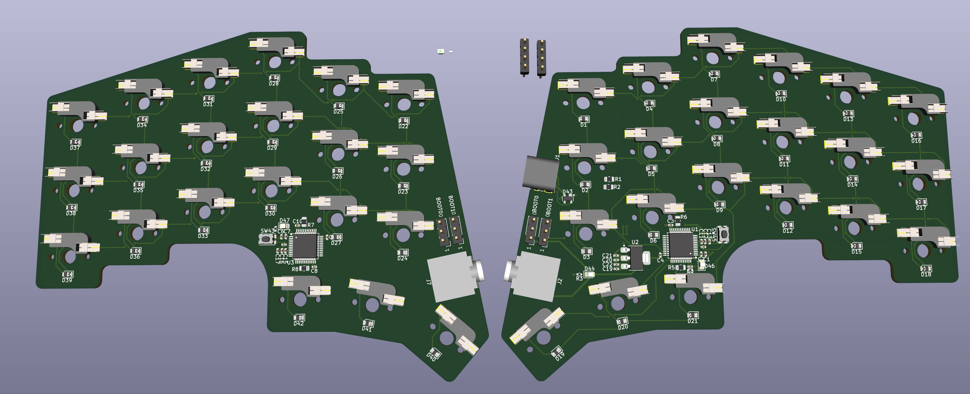
Designed from scratch in KICAD
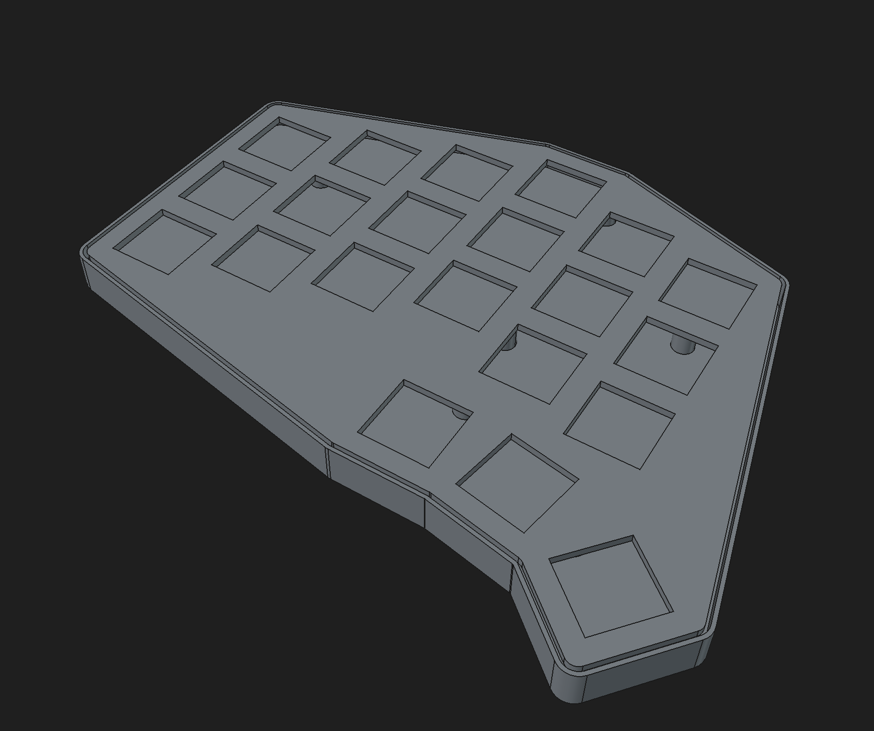
Custom case designed in FreeCAD and 3D printed
Custom firmware the will be written in rust
firmware/ - Keyboard firmwarepcb/ - PCB design filesartifacts/ - STLs, DXFs, and other exported filesscreenshots/ - Screenshots of various parts during development| Qty | Value | Footprint | References |
|---|---|---|---|
| 42 | D | Diode_SMD:D_0805_2012Metric | D1, D2, D10, D11, D12, D13, D14, D15, D16, D17, D18, D19, D20, D21, D22, D23 +26 |
| 42 | SW_Push | MyLibrary:MX100H | SW1, SW2, SW10, SW11, SW12, SW13, SW14, SW15, SW16, SW17, SW18, SW19, SW20, SW21, SW22, SW23 +26 |
| 14 | 100nF | Capacitor_SMD:C_0402_1005Metric | C3, C4, C5, C6, C7, C8, C9, C10, C11, C12, C13, C14, C15, C16 |
| 14 | MountingHole | MountingHole:MountingHole_3mm | H1, H2, H3, H4, H5, H6, H7, H8, H9, H10, H11, H12, H13, H14 |
| 4 | 0.1uF | Capacitor_SMD:C_0402_1005Metric | C19, C20, C21, C22 |
| 4 | 100R | Resistor_SMD:R_0402_1005Metric | R3, R4, R5, R6 |
| 4 | 10k | Resistor_SMD:R_0805_2012Metric | R7, R8, R9, R10 |
| 4 | LED | LED_SMD:LED_0805_2012Metric | D44, D45, D46, D47 |
| 2 | 1uF | Capacitor_SMD:C_0402_1005Metric | C17, C18 |
| 2 | 5.1k | Resistor_SMD:R_0805_2012Metric | R1, R2 |
| 2 | BOOT0 | Connector_PinHeader_2.54mm:PinHeader_1x03_P2.54mm_Vertical | J2, J4 |
| 2 | BOOT1 | Connector_PinHeader_2.54mm:PinHeader_1x03_P2.54mm_Vertical | J3, J5 |
| 2 | Debug UART | Connector_PinHeader_2.54mm:PinHeader_1x04_P2.54mm_Vertical | J6, J7 |
| 2 | STM32F103C8Tx | Package_QFP:LQFP-48_7x7mm_P0.5mm | U2, U3 |
| 2 | SW_Push | Button_Switch_SMD:SW_Push_1P1T_NO_CK_KMR2 | SW43, SW44 |
| 1 | 10uF | Capacitor_SMD:C_0402_1005Metric | C1 |
| 1 | 4.7uF | Capacitor_SMD:C_0402_1005Metric | C2 |
| 1 | AMS1117-3.3 | Package_TO_SOT_SMD:SOT-223-3_TabPin2 | U1 |
| 1 | SP0503BAHT | Package_TO_SOT_SMD:SOT-143 | D43 |
| 1 | USB_C_Receptacle_USB2.0_16P | Connector_USB:USB_C_Receptacle_GCT_USB4085 | J1 |
It measures 261 × 101.9 mm and has 2 copper layers, 1.6 mm thick.
147 parts, built around the AMS1117-3.3 and SP0503BAHTG. The full list of its parts is on this page, with links to each part's symbol and footprint where PCBKit's library has them.
From the adlwar137/Keyboard repository on GitHub, at the commit this page was made from: the board is PCB/Keyboard-PCB.kicad_pcb and its schematic PCB/Keyboard-PCB.kicad_sch. PCBKit opens the board in the browser, with nothing to install.
Its repository states no licence, so its author keeps all rights: ask adlwar137 before reusing the design.
fossasia/pslab-hardware
PSLab Hardware Design and Schematics https://pslab.io


maddevsio/mad-navigator
Mad navigator is simple compass-like device shows direction to predefined geo point. This repository contains firmware source code and schematics for device.

GabrielD98/PickUS_and_PlacUS
pick and place de PCB pour projet S4 de robotique

kwartzlab/Environmental-Sensor
The source for the environmental sensors used at Kwartzlab

FireLabsCA/HabitatCAN-Dev-Board-ESP32
HabitatCAN development board with ESP32 microprocessor

t3mschm2d/esp32-tiny-led-controller
The main goal of this project is to develop an OpenHardware board for controlling digital LED strips. The control shall be done via Homeassistant and esphome.The PCB is based around an ESP32-U4WDH microcontroller and…

zademahi238/mission-mimosa
To answer this, we compare task-completion success rates with and without tactile sensing across different robot-learning policies.