2 layers69 × 79 mm
NTC
xuejun7777/Comprehensive-Design-and-Practice-Project-A---Digital-Thermometer-Based-on-NTC
综合设计与实践A项目-基于NTC的数字温度计
44 parts2

 adbik4/DL-FinalProject
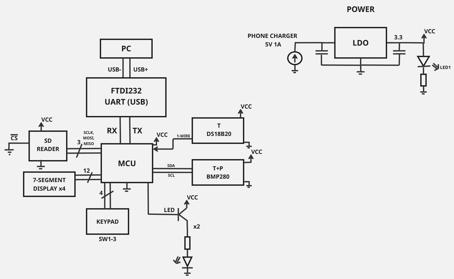
The design and implementation of a measurement and data logging system based on ATmega328pb microcontroller. The system is intended for measuring temperature and pressure using dedicated digital sensors: DS18B20 and BMP280. The captured data can be displayed on a 7-segment display and transmitted to a PC via USB-UART interface.
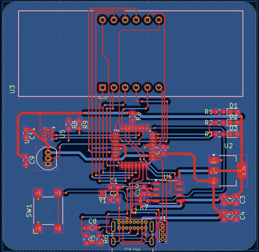
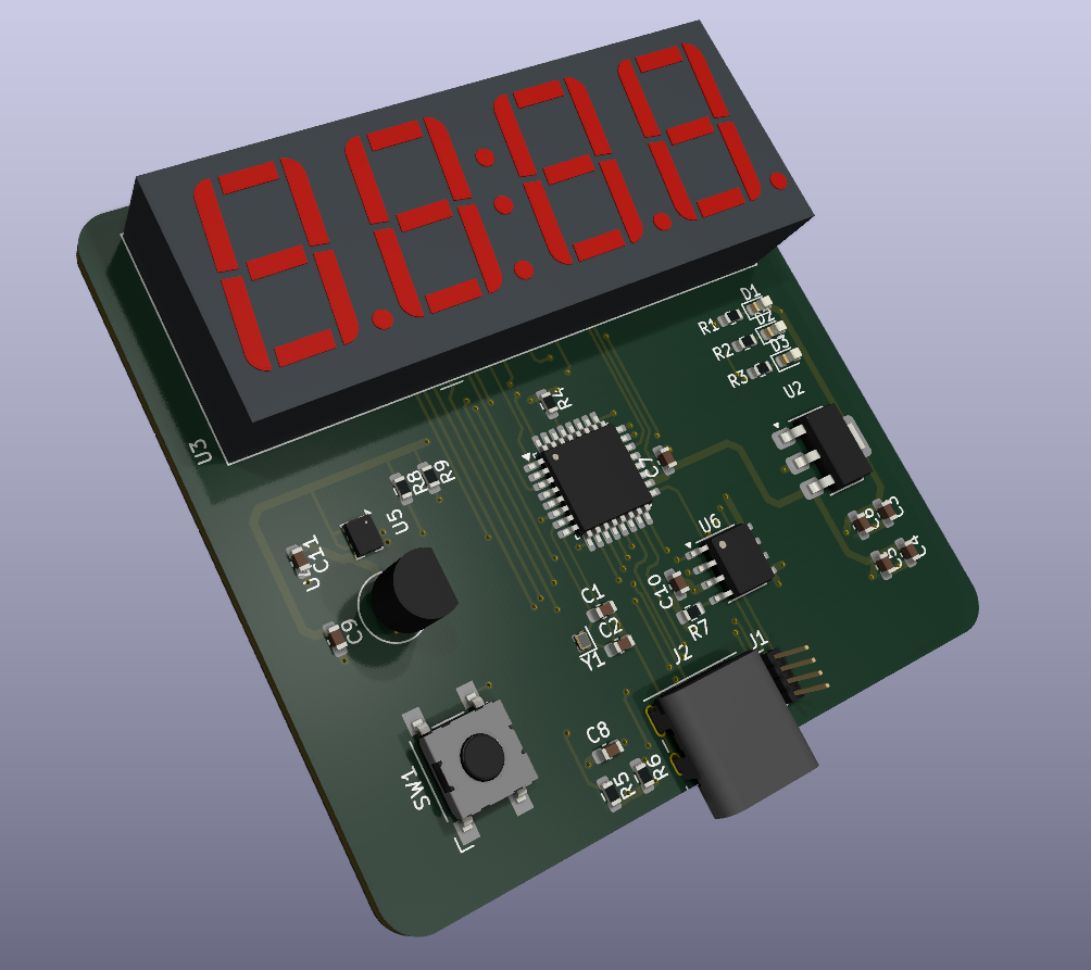
DesignLab semV is an open-source printed circuit board by adbik4, from the adbik4/DL-FinalProject repository on GitHub. It is a 2-layer board of 57 × 55.8 mm with 33 parts on 44 nets, routed with 457 tracks and 94 vias.
It is built around the ATMEGA328PB-AU, BMP280 and CH340N, with the DS18B20, AMS1117-3.3 and CC56-12EWA among its other parts. Its parts include 11 capacitors, 9 resistors, 6 ICs, 3 diodes and 2 connectors. It belongs with the sensors and measurement and interfaces and adapters boards and the AVR (ATmega, ATtiny) boards of this library.


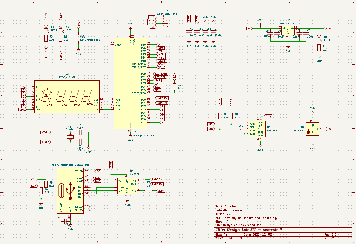
Obliczanie wartości pojemności C1 i C2 potrzebnych do zewnętrznego oscylatora MCU:
Wybraliśmy CY16BPS ponieważ jego parametry należą do najpopularniejszych do użycia w projektach z tym MCU.
Oto jego najważniejsze parametry:
Dla uproszczenia obliczeń, niech C1 = C2.
Korzystając ze wzoru z dokumentacji ATmega,
C = 2 * C_L + C_S
gdzie
C_L - Pojemnosć obciążenia kryształu,
C_S - Pojemność pasożytnicza płytki PCB, niech wynosi 2 pF
Dla naszego kryształu C_L wynosi 20 pF
Stąd wynika, że C powinno mieć wartość około 42 pF.
Obliczanie wartości rezystancji R1, R2 i R3 potrzebnych do uregulowania pracy diód:
Napięcie zasilania: 3.3V
Kolor diód LED: zielony co oznacza spadek napięcia około 2.2V
Chcemy ustalić bezpieczny punkt pracy, powiedzmy 10mA
Z prawa ohma: R = U / I = (3.3 - 2.2) / 10 mA = 110 ohm
Wartość rezystancji podciągającej dla I2C jest wymianą pomiędzy możliwą prędkością wymiany danych a zużyciem energii.
Zbyt mała wartość może uniemożliwić pinowi układu scalonego z którym się komunikujemy zwarcie linii z masą. Zalezy ona więc od najniższego napięcia jaka może być odczytana przez dany ukł. (U_OL) oraz prądu jaki jest on w stanie wytrzymać (I_OL).
R_min = (V_CC - U_OLmax) / I_OL
Zbyt duża zaś, przy dużych prędkościach może nie nadążyć z naładowaniem pojemności magistrali (C_m) przed nadejściem kolejnego stanu niskiego. W związku z tym, zależy ona od czasu narastania zboczy.
R_max = t_r / (0.8473 * C_m)
Wartość 0.8473 = -ln(0.3) wynika z czasu ładowania pojemności od 30% - 70%
Przy naszych małych prędkościach komunikacji oraz z pojedynczym urządzeniem na magistrali, przyjmiemy standardową wartość 4.7kΩ.
| Qty | Value | Footprint | References |
|---|---|---|---|
| 6 | 100n | Capacitor_SMD:C_0603_1608Metric | C5, C6, C7, C9, C10, C11 |
| 3 | 110 | Resistor_SMD:R_0603_1608Metric | R1, R2, R3 |
| 2 | 1k | Resistor_SMD:R_0603_1608Metric | R4, R7 |
| 2 | 4.7k | Resistor_SMD:R_0603_1608Metric | R8, R9 |
| 2 | 42pF | Capacitor_SMD:C_0603_1608Metric | C1, C2 |
| 2 | 5.1k | Resistor_SMD:R_0603_1608Metric | R5, R6 |
| 1 | 10uF | Capacitor_SMD:C_0603_1608Metric | C4 |
| 1 | 1n | Capacitor_SMD:C_0603_1608Metric | C8 |
| 1 | 22uF | Capacitor_SMD:C_0603_1608Metric | C3 |
| 1 | AMS1117-3.3 | Package_TO_SOT_SMD:SOT-223-3_TabPin2 | U2 |
| 1 | ATmega328PB-A | Package_QFP:TQFP-32_7x7mm_P0.8mm | U1 |
| 1 | BMP280 | Package_LGA:Bosch_LGA-8_2x2.5mm_P0.65mm_ClockwisePinNumbering | U5 |
| 1 | CC56-12EWA | Display_7Segment:CA56-12EWA | U3 |
| 1 | CH340N | Package_SO:JEITA_SOIC-8_3.9x4.9mm_P1.27mm | U6 |
| 1 | Conn_01x04_Pin | Connector_PinHeader_1.00mm:PinHeader_1x04_P1.00mm_Vertical | J1 |
| 1 | Crystal | Crystal:Crystal_SMD_1210-4Pin_1.2x1.0mm | Y1 |
| 1 | DS18B20 | Package_TO_SOT_THT:TO-92_Inline | U4 |
| 1 | LED1 | LED_SMD:LED_0603_1608Metric | D1 |
| 1 | LED2 | LED_SMD:LED_0603_1608Metric | D2 |
| 1 | LED3 | LED_SMD:LED_0603_1608Metric | D3 |
| 1 | SW_Omron_B3FS | Button_Switch_SMD:SW_SPST_Omron_B3FS-100xP | SW1 |
| 1 | USB_C_Receptacle_USB2.0_16P | Connector_USB:USB_C_Receptacle_GCT_USB4085 | J2 |
It measures 57 × 55.8 mm and has 2 copper layers, 1.6 mm thick.
33 parts, built around the ATMEGA328PB-AU, BMP280, CH340N and DS18B20. The full list of its parts is on this page, with links to each part's symbol and footprint where PCBKit's library has them.
From the adbik4/DL-FinalProject repository on GitHub, at the commit this page was made from: the board is KiCad_DesignLab_AK_AB_SS/DesignLab_semV.kicad_pcb and its schematic KiCad_DesignLab_AK_AB_SS/DesignLab_semV.kicad_sch. PCBKit opens the board in the browser, with nothing to install.
Its repository states no licence, so its author keeps all rights: ask adbik4 before reusing the design.
xuejun7777/Comprehensive-Design-and-Practice-Project-A---Digital-Thermometer-Based-on-NTC
综合设计与实践A项目-基于NTC的数字温度计

syeedameen/miniflight
Budget Flight Controller for Drones with ATmega328P Microcontroller


enragedcanadiangoose/7-Segment-Thermometer
A simple project using 2 onewire thermal sensors an arduino nano and a 4 digit common cathode 7 segment display


