2 layers52.3 × 12 mm
UARTStick
hardik1975/UARTStick
Say hello to UART Stick — a micro-sized, Arduino-compatible USB to UART converter designed for makers, tinkerers, and embedded developers.
25 parts2

 adaptableCoder/USB-to-UART-CH340g-PCB2
PCB design for USB-to-UART converter based on CH340G with a USB-A edge connector.
USB to UART is an open-source printed circuit board by adaptableCoder, from the adaptableCoder/USB-to-UART-CH340g-PCB repository on GitHub, published under the MIT licence. It is a 2-layer board of 57.3 × 12 mm with 28 parts on 24 nets, routed with 176 tracks and 22 vias.
It is built around the CH340G, SPX3819M5-L-3-3 and USBLC6-2SC6. Its parts include 8 capacitors, 3 resistors, 3 ICs, 3 diodes and 2 connectors. It belongs with the interfaces and adapters boards of this library.


A compact USB-to-UART adapter based on the CH340G, implemented as a USB-A edge connector board. Fabrication files have been generated; board fabrication is pending.
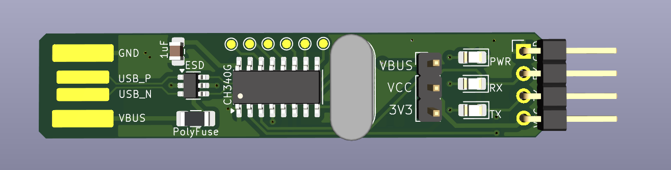
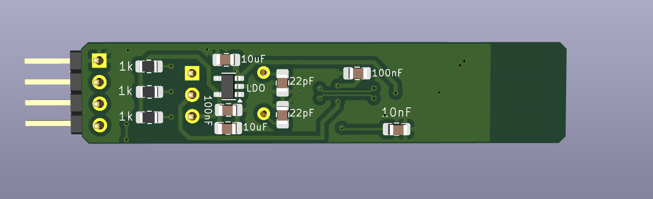
This project implements a reliable USB-to-UART interface suitable for development, debugging, and embedded bring-up tasks. Unlike typical breakout boards, this design uses a USB-A edge connector, allowing direct insertion into a host USB port without a cable.
The board supports both 5 V and 3.3 V UART logic levels via jumper selection.
Grounding strategy
Clock integrity
Manufacturability
usb-to-uart-ch340g-pcb/
├── README.md
├── LICENSE
├── docs/
│   ├── images/
│   └── design-notes.md
├── schematic/
│   └── usb-to-uart-ch340g_schematic.pdf
├── pcb/
│   └── layout_screenshots/
├── fabrication/
│   ├── USB-to-UART-CH340G_Gerbers.zip
│   └── fab-notes.txt
├── datasheet/
│   └── CH340G_datasheet.pdf
└── KiCAD files/
    ├── usb-to-uart.kicad_pro
    ├── usb-to-uart.kicad_sch
    ├── usb-to-uart.kicad_prl
└── usb-to-uart.kicad_pcbThe USB-A edge connector footprint is adapted from an open-source KiCad footprint library. The original library is referenced here for attribution: https://github.com/vasya-zh/PCB-Edge-USB-connector-KiCad-library
Component selection and implementation follow the WCH CH340G datasheet and standard USB Full-Speed design guidelines.
Some YouTube tutorials and online articles on USB-to-UART designs were consulted during development.
PCB Cupid
Hardik Seth
Electronics Globe
This project is released under the MIT License unless stated otherwise. Third-party references retain their respective licenses.
This project was built as a practical hardware design exercise, with emphasis on finishing a complete, manufacturable PCB rather than producing a minimal demo board. Future revisions may explore USB-C support or auto-voltage sensing.
| Qty | Value | Footprint | References |
|---|---|---|---|
| 6 | TestPoint | TestPoint:TestPoint_Pad_D1.0mm | TP1, TP2, TP3, TP4, TP5, TP6 |
| 3 | 1k | Resistor_SMD:R_0805_2012Metric_Pad1.20x1.40mm_HandSolder | R1, R2, R3 |
| 2 | 100nF | Capacitor_SMD:C_0805_2012Metric_Pad1.18x1.45mm_HandSolder | C5, C8 |
| 2 | 10uF | Capacitor_SMD:C_0805_2012Metric_Pad1.18x1.45mm_HandSolder | C4, C6 |
| 2 | 22pF | Capacitor_SMD:C_0805_2012Metric_Pad1.18x1.45mm_HandSolder | C1, C2 |
| 1 | 10nF | Capacitor_SMD:C_0805_2012Metric_Pad1.18x1.45mm_HandSolder | C3 |
| 1 | 1uF | Capacitor_SMD:C_0805_2012Metric_Pad1.18x1.45mm_HandSolder | C9 |
| 1 | CH340G | Package_SO:SOIC-16_3.9x9.9mm_P1.27mm | U1 |
| 1 | Conn_01x04_Pin | Connector_PinHeader_2.54mm:PinHeader_1x04_P2.54mm_Horizontal | J3 |
| 1 | Crystal | Crystal:Crystal_HC49-U_Vertical | Y1 |
| 1 | Jumper_3_Open | Connector_PinHeader_2.54mm:PinHeader_1x03_P2.54mm_Vertical | JP1 |
| 1 | Polyfuse_Small | Fuse:Fuse_1206_3216Metric_Pad1.42x1.75mm_HandSolder | F1 |
| 1 | Power LED | LED_SMD:LED_0805_2012Metric_Pad1.15x1.40mm_HandSolder | D1 |
| 1 | Rx_LED | LED_SMD:LED_0805_2012Metric_Pad1.15x1.40mm_HandSolder | D2 |
| 1 | SPX3819M5-L-3-3 | Package_TO_SOT_SMD:SOT-23-5 | U3 |
| 1 | Tx_LED | LED_SMD:LED_0805_2012Metric_Pad1.15x1.40mm_HandSolder | D3 |
| 1 | USBLC6-2SC6 | Package_TO_SOT_SMD:SOT-23-6 | U2 |
| 1 | USB_A_PCB_Edge_receptacle | Connector_USB_PCB_Edge:USB_A_PCB_Edge_receptacle | J1 |
It measures 57.3 × 12 mm and has 2 copper layers, 1.6 mm thick.
28 parts, built around the CH340G, SPX3819M5-L-3-3 and USBLC6-2SC6. The full list of its parts is on this page, with links to each part's symbol and footprint where PCBKit's library has them.
From the adaptableCoder/USB-to-UART-CH340g-PCB repository on GitHub, at the commit this page was made from: the board is KiCAD Files/USB-to-UART.kicad_pcb and its schematic KiCAD Files/USB-to-UART.kicad_sch. PCBKit opens the board in the browser, with nothing to install.
Its repository publishes it under the MIT licence: you may reuse it on that licence's terms (keep the author's notice, and for a copyleft licence share your changes alike).
hardik1975/UARTStick
Say hello to UART Stick — a micro-sized, Arduino-compatible USB to UART converter designed for makers, tinkerers, and embedded developers.

ffich/ESPRocks_KURT
This is the HW repository that contains the ESPRocks KURT board HW design.

eritbh/esp01-led-controller
Using the ESP-01 to control addressable RGB LED strips.


bassammorsy/stm32-flight-controller
Custom 4-layer STM32F405RGTx quadcopter flight controller PCB designed in KiCad. Betaflight compatible, 4S–6S LiPo input, SMT assembled by JLCPCB.

