2 layers100 × 52.5 mm
 acwright/KEY2USB4
Commodore 64 / C128 expansion port cartridge to USB HID keyboard
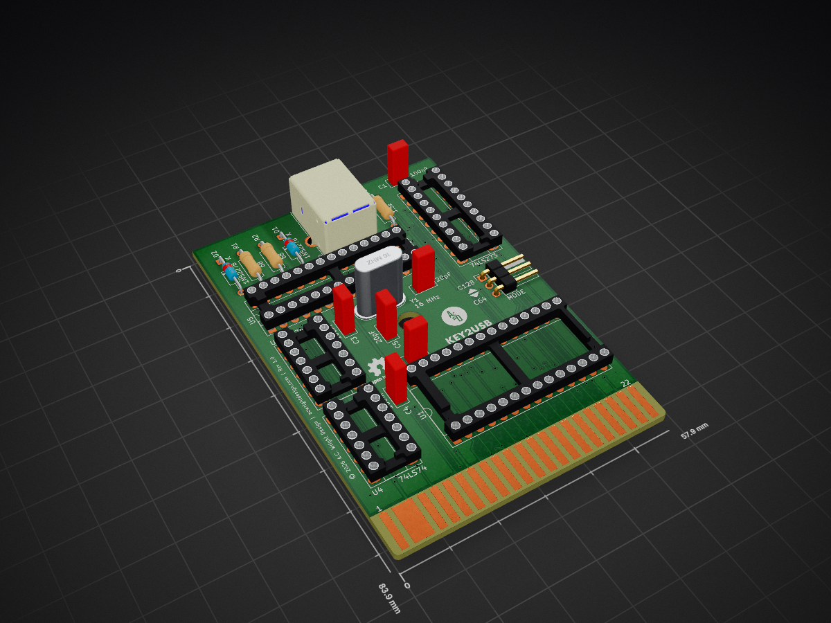
KEY2USB is an open-source printed circuit board by acwright, from the acwright/KEY2USB repository on GitHub, published under the CERN-OHL-P-2.0 licence. It is a 2-layer board of 57.9 × 83.9 mm with 23 parts on 74 nets, routed with 415 tracks and 116 vias.
It is built around the ATMEGA328-PU, 74LS273PC and 74LS32SC, with the 74LS74PC and 1N5227B among its other parts. Its parts include 6 capacitors, 5 ICs, 3 resistors, 3 connectors and 2 diodes. It belongs with the retro computing and games and keyboards and input boards and the AVR (ATmega, ATtiny) boards of this library.


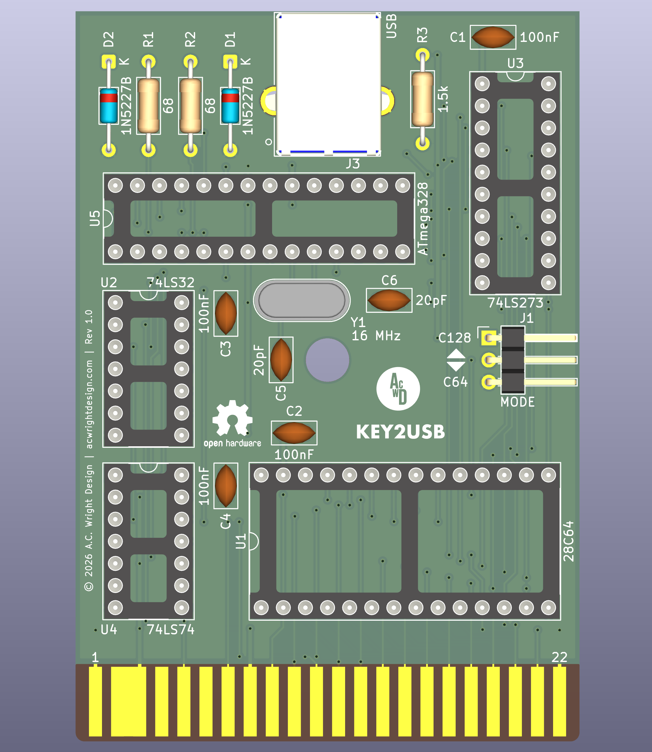
A non-invasive Commodore 64 expansion port cartridge that lets the machine's own physical keyboard act as a USB HID keyboard for a connected PC running the VICE emulator. Plug it in, power on the C64, connect a USB cable — no case modification, no soldering into the keyboard.
KEY2USB is a C64 cartridge that solves a specific problem: when running the VICE emulator on a PC alongside a real Commodore 64, you can't easily use the C64's authentic keyboard as a USB input device without modifying the machine. KEY2USB plugs into the expansion port and bridges the C64's keyboard matrix — read by the C64's own 6502 — to a USB HID keyboard interface, using no invasive hardware modifications.
Nothing inside the machine is touched. The cartridge takes over the C64 on power-up, scans the keyboard matrix itself, and reports every make/break to the PC as a standard USB HID boot keyboard. Power comes from the expansion port; the only cable is USB.
| Machine | Supported | Notes |
|---|---|---|
| Commodore 64 (all revisions) | Yes | Primary target |
| Commodore 64C | Yes | Identical keyboard matrix |
| Commodore 128 / 128D | Yes | Runs in C64 mode — see below. Verified on real hardware |
| Ultimate 64 | Yes | Verified on real hardware |
On a C128, the cartridge asserts /EXROM, which the C128 detects at reset and
uses to boot straight into C64 mode — so KEY2USB comes up on its own with no key
combination needed. Every key the C128 shares with the C64 works normally; the
C128's extra keys (numeric keypad, ESC, TAB, ALT, HELP, LINE FEED, NO SCROLL, the
separate cursor pad, CAPS LOCK and 40/80 DISPLAY) are not reported in C64 mode.
For the full C128 keyboard in VICE's x128, move the mode jumper
to C128: the cartridge then runs in native C128 mode and reports all 91 keys. See
x128.
If a particular C128 does not autostart, power on while holding the C= key to force C64 mode.
KEY2USB splash screen appears; the cartridge has taken
over the machine and is scanning the keyboard.While KEY2USB is running, the C64 is dedicated to being a keyboard — it does not return to BASIC. Power off and remove the cartridge to use the machine normally.
/EXROM state are selected together by a single MODE jumper, set to C64 on shipping units — see Mode Jumper./IO1 + R/W; a 74LS273 (8-bit D flip-flop register) latches the key-event byte the 6502 firmware writes to $DE00; a 74LS74 (dual D flip-flop) provides a single RDY handshake flag.RDY flag, and sends 8-byte USB HID boot-protocol keyboard reports. A 16 MHz crystal clocks the MCU.The two sides share only a single byte-wide latch and one ready flag — no shared clock or bus timing requirements.
The board carries a 3-pin MODE header (J1) that selects the EEPROM bank and the
/EXROM state together:
| Jumper position | EEPROM bank | /EXROM | Behavior |
|---|---|---|---|
| C64 (GND) — factory default | Lower 4K | Asserted | Autostarts via the CBM80 signature. On a C128, forces a boot into C64 mode. |
| C128 (+5V) | Upper 4K | Released | Autostarts as a C128 external function ROM in native mode. |
Assembled cartridges ship with the jumper set to C64 and the case closed over it. The C64 bank is the supported configuration; it covers the C64, C64C, Ultimate 64, and the C128 by way of C64 mode. There is no need to change it, and the case has no opening for it.
The C128 bank is for C128 owners who want the whole C128 keyboard in x128:
the 8×8 matrix plus the numeric keypad, ESC, TAB, ALT, HELP, LINE FEED, NO SCROLL,
the cursor pad, CAPS LOCK and 40/80 DISPLAY. It is verified on a real C128 (every
key, in x128 too). It has no use on a C64. Changing the jumper means opening the
case, and is entirely at your own discretion.
This repository contains the KiCad 10.0 PCB design for the KEY2USB board.
Hardware/
A single cartridge PCB hosting the ROM, glue logic, and USB MCU. Provides:
WRSTB from /IO1 + R/W$DE00RDY//CLRRDY flag/EXROM, lower 4K EEPROM bank); see Mode JumperRev 1.0
Both firmwares are implemented in Firmware/ (see Firmware/README.md for build,
flash, and layout details). Set VICE's keyboard mapping to Positional — see
VICE Setup.
6502 side (C64 bank — the shipping configuration):
CBM80 signature, take over the machine, and draw a centered KEY2USB splash on the 40-column screen.$DC00/$DC01) for raw make/break events and modifier state — no KERNAL buffer.$DE00.The upper bank holds the C128 native-mode firmware, which autostarts from a
CBM / $01 external function ROM header. It scans the 8×8 matrix, the three extra
key columns via $D02F, and the CAPS LOCK and 40/80 DISPLAY latches, and tells the
ATmega to use x128's host keys. See Firmware/Cart/README.md.
ATmega328/328P side:
RDY; on set, read the key byte from PINC/PINB, pulse /CLRRDY.One setting trips people up every time, so set it before anything else:
Keyboard mapping must be Positional, not Symbolic. In VICE: Settings → Keyboard → Keyboard Mapping → Positional. This is the single most common first-time setup mistake — if keys look wrong, check this first. The reason is worth understanding, because it explains the whole signal path:
A USB keyboard never transmits characters. Press A and it sends HID usage
0x04; the USB spec names that "Keyboard a and A", but the name is only
documentation — the code means "the key where a US keyboard has A". Your OS
decides it is an A by applying the selected layout. On AZERTY the same key
sends the same 0x04 and the OS renders Q.
KEY2USB is positional end to end for exactly that reason. The 6502 detects a
key by matrix position (col*8 + row) and never computes a character; the
ATmega looks that keyID up in keymap.h and emits the HID usage for the PC key
in the corresponding physical spot; VICE's Positional keymap maps PC positions
back onto C64 matrix positions. Positions in, positions through, positions out
— nothing resolves to a character until VICE finally does it.
Symbolic breaks that chain by inserting a translation. Press SHIFT + 2,
which is " on a C64. The cartridge sends shift plus the position code for
2; the host applies its US layout and concludes you typed @. Symbolic then
asks "which C64 key produces @?" and presses that one — wrong. Positional
ignores the character entirely, sees "physical shift + physical 2", and gives
you the " you actually pressed. The keystroke arrived correctly either way;
Symbolic just did an unwanted extra translation using a PC layout that does
not match a C64's.
USB HID reports are sent as a standard boot-protocol keyboard — no special VICE driver or configuration is needed beyond the keymap.
Both joystick ports are scanned by the cartridge and arrive at the host as ordinary keystrokes, so VICE has to be told which keys mean "joystick". Everything lives on the numeric keypad, split so the two ports cannot collide.
First tick Settings → Joystick → Allow keyset joysticks. Without it VICE
ignores both the Numpad device and keysets, and the stick just types keypad
keys. VICE keeps this setting separately for each emulator (x64sc, x128 …),
so set it in each one you use.
Port 2 — the easy one, nothing else to configure:
Settings → Joystick → Joystick Port #2 → Numpad (called Keypad in some VICE versions)
VICE's built-in Numpad device already maps keypad digits (8/2/4/6 for
directions, 7/9/1/3 for diagonals, 0/5 for fire), and the cartridge's
port-2 mapping was chosen to match it exactly.
Port 1 — needs a keyset, because Numpad can only serve one port:
Settings → Joystick → Joystick Port #1 → Keyset A, then Configure Keyset A:
| Direction | Key |
|---|---|
| North | Keypad − |
| South | Keypad + |
| West | Keypad / |
| East | Keypad * |
| Fire | Keypad enter |
Port 1 uses keypad symbols rather than digits or function keys for two reasons: the digits are already claimed by the Numpad device serving port 2, and VICE's positional keymap binds F12 to RESTORE, so a function-key keyset cannot use it. The symbols are untouched by both.
RESTORE is not part of the keyboard matrix (it pulls the C64's NMI line), but the cartridge reports each press anyway, as Page Up — the key VICE's positional keymap uses for RESTORE. RUN/STOP + RESTORE works in the emulator with no configuration.
A held joystick direction grounds a line in the keyboard matrix, so it also phantom-presses real keys — exactly as it does on a real C64. This is inherent to the wiring, not a firmware choice, and it is left in place so the cartridge behaves like the bare machine.
It hits port 1 hardest: a held direction grounds a matrix row, pressing all 8 keys in it — which includes RETURN, INST/DEL and CLR/HOME. Expect stray keystrokes while a port-1 direction is held. Port 2 is the one to use in practice; it grounds a column instead, which only aliases if you are also pressing a key in that same column.
Software/key2usbtest.prg shows live joystick state for both ports plus the
last keys received, so you can confirm the cartridge and your VICE
configuration in one place. On a Mac, Software/key2usbmon checks the
cartridge itself with VICE out of the picture: it reads the raw USB reports and
names the C64 key behind each one. See Software/.
x128 (C128 native mode)With the mode jumper on C128, the cartridge runs in native C128
mode and the ATmega switches to the host keys VICE's x128 positional keymap
expects. Use Settings → Keyboard → Keyboard Mapping → Positional here too.
| C128 key | Host key | C128 key | Host key | |
|---|---|---|---|---|
| F1 / F3 / F5 / F7 | F1 / F2 / F3 / F4 | ESC | F9 | |
| HELP | F5 | TAB | F10 | |
| LINE FEED | F6 | ALT | F11 | |
| 40/80 DISPLAY | F7 (tap) | CAPS LOCK | F12 (tap) | |
| NO SCROLL | F8 | Numeric keypad | Keypad | |
| Cursor pad | Arrow keys | RESTORE | Page Up |
Three things behave differently from C64 mode:
x128 drives only the separate cursor pad from the
host arrows, and SHIFT does not reverse it. The cartridge therefore sends the
main CRSR keys as Right/Down, or Left/Up while SHIFT is held, so they move the
cursor exactly as on the real machine.x128 toggles them on
each host key press. Each movement of the latch is sent as one tap, so x128
follows the real key. If they ever disagree, toggle the key twice. 40/80 only
takes effect at reset, as on the real machine.Software/key2usbmon --c128 --check checks all 89 keys from the host side, and
Software/key2usbtest128.prg (BASIC 7.0, run inside x128) names each key x128
sees, plus the CAPS LOCK and 40/80 state.
xvic)The cartridge also drives VICE's VIC-20 emulator, with the same Positional
setting and no keymap changes. This works because VICE's two positional keymaps
are the same map in different coordinates — VIC20/gtk3_pos.vkm states the
relationship outright:
# to convert from C64 to VIC20:
# change rows 7 -> 0, 0 -> 7
# change columns 7 -> 3, 3 -> 7
Applying that permutation and diffing the two files (VICE 3.x, GTK3, US layout) gives:
| Host keysyms in each map | 151 / 151 |
| Present in one but not the other | 0 |
| Agree under the permutation | 150 |
| Differ | 1 |
The lone difference is cosmetic: > sits at matrix position 5 4 in both, but
carries shiftflag 1 on the C64 ("combined with shift") and 8 on the VIC-20
("can be shifted or not"). The cartridge sends the physical . key and physical
SHIFT as separate events, so both yield > regardless. The RESTORE entries
(Page_Up / F12 / Prior) and all twenty joyport keypad entries are identical.
Both emulators therefore consume the same host keys and route them to the
same-labelled machine keys. keymap.h is built as the inverse of the C64
positional map, which makes it equally the inverse of the VIC-20 one.
Two caveats:
xvic. The mapping is confirmed; end-to-end behaviour is not.Software/
Host-side test software:
key2usbmon (macOS) reads the cartridge's raw USB reports directly, with no
emulator involved, and names the C64 key behind each one. --check runs a
press-every-key checklist. Build with make key2usbmon (requires swiftc
from the Xcode Command Line Tools).key2usbtest.prg runs inside VICE and shows live joystick state for both
ports plus the last keystrokes received, so you can verify your VICE
configuration. Build with make key2usbtest.prg (requires petcat, which
ships with VICE) or use the prebuilt .prg.key2usbtest128.prg is the BASIC 7.0 equivalent for x128 in C128 mode (mode
jumper on C128). It names every C128 key x128 sees, including the keypad and
the other extra keys, plus the CAPS LOCK and 40/80 state.See Software/README.md.
CAD/
3D models and render images for the KEY2USB board.
Production/
JLCPCB-ready fabrication files, BOM, and component positions for PCB fabrication.
Schematics/
PDF schematic for the KEY2USB board.
Libraries/
Custom KiCad symbol and footprint libraries, including the C64 expansion port edge connector footprint and the USB Type B connector footprint.
| Reference | Qty | Value | Description | Digikey |
|---|---|---|---|---|
| C1, C2, C3, C4 | 4 | 100nF | Ceramic disc capacitor — IC bypass | 478-5732-ND |
| C5, C6 | 2 | 20pF | Ceramic disc capacitor — crystal load | 478-7724-ND |
| D1, D2 | 2 | 1N5227B | 3.6V Zener diode, DO-35 — USB line clamp | 1N5227B-ND |
| J1 | 1 | MODE | 3-pin 2.54mm header + jumper cap — mode select, factory-set to C64 | S1121EC-03-ND |
| J2 | 1 | C64 EXP PORT | C64 expansion port edge connector (44-pin, 3.96mm pitch) | |
| J3 | 1 | USB | USB Type B connector, through-hole (UJ2-BH-BL1-TH) | 102-5886-ND |
| R1, R2 | 2 | 68Ω | Resistor, 1/4W — USB D+ / D− series | S68CACT-ND |
| R3 | 1 | 1.5kΩ | Resistor, 1/4W — USB D− pull-up to +5V | S1.5KCACT-ND |
| U1 | 1 | 28C64 | 8K×8 EEPROM, DIP-28 — holds C64 and C128 firmware banks | AT28C64B-15PU-ND |
| U2 | 1 | 74LS32 | Quad 2-input OR gate, DIP-14 — generates write strobe | 296-1658-5-ND |
| U3 | 1 | 74LS273 | 8-bit D flip-flop register, DIP-20 — key-event latch | 296-1657-5-ND |
| U4 | 1 | 74LS74 | Dual D flip-flop, DIP-14 — RDY handshake flag | 296-1668-5-ND |
| U5 | 1 | ATmega328P-PU | 8-bit AVR MCU, DIP-28 — V-USB and HID firmware | ATMEGA328-PU-ND |
| Y1 | 1 | 16 MHz | Crystal, through-hole — ATmega328P clock | 3155-16M20P2/49US-ND |
KEY2USB is available as a kit on Tindie for those who would rather not order boards from a fab and source parts themselves.

Hardware designs are released under the CERN Open Hardware Licence Version 2 – Permissive.
The cartridge ROM firmware (Firmware/Cart/) and the controller firmware's own
sources (Firmware/Controller/src/, include/) are MIT-licensed. The controller
firmware links the vendored V-USB driver, which is
GPL v2/v3, so the built controller firmware image is distributed under the GPL;
this repository is its corresponding source.
| Qty | Value | Footprint | References |
|---|---|---|---|
| 4 | 100nF | Capacitor_THT:C_Disc_D5.0mm_W2.5mm_P2.50mm | C1, C2, C3, C4 |
| 2 | 1N5227B | Diode_THT:D_DO-35_SOD27_P10.16mm_Horizontal | D1, D2 |
| 2 | 20pF | Capacitor_THT:C_Disc_D5.0mm_W2.5mm_P2.50mm | C5, C6 |
| 2 | 68 | Resistor_THT:R_Axial_DIN0207_L6.3mm_D2.5mm_P10.16mm_Horizontal | R1, R2 |
| 1 | 1.5k | Resistor_THT:R_Axial_DIN0207_L6.3mm_D2.5mm_P10.16mm_Horizontal | R3 |
| 1 | 16 MHz | Crystal:Crystal_HC49-U_Vertical | Y1 |
| 1 | 28C64 | Package_DIP:DIP-28_W15.24mm_Socket_LongPads | U1 |
| 1 | 74LS273 | Package_DIP:DIP-20_W7.62mm_Socket_LongPads | U3 |
| 1 | 74LS32 | Package_DIP:DIP-14_W7.62mm_Socket_LongPads | U2 |
| 1 | 74LS74 | Package_DIP:DIP-14_W7.62mm_Socket_LongPads | U4 |
| 1 | ATmega328 | Package_DIP:DIP-28_W7.62mm_Socket_LongPads | U5 |
| 1 | C64 EXP PORT | KEY2USB:C64_EXPANSION_PORT | J2 |
| 1 | LOGO | A.C. Wright Logo:A.C. Wright Logo 5mm | G*** |
| 1 | MODE | Connector_PinHeader_2.54mm:PinHeader_1x03_P2.54mm_Horizontal | J1 |
| 1 | USB | KEY2USB:UJ2-BH-BL1-TH | J3 |
The 21 most common of 23 parts.
It measures 57.9 × 83.9 mm and has 2 copper layers, 1.6 mm thick.
23 parts, built around the ATMEGA328-PU, 74LS273PC, 74LS32SC and 74LS74PC. The full list of its parts is on this page, with links to each part's symbol and footprint where PCBKit's library has them.
From the acwright/KEY2USB repository on GitHub, at the commit this page was made from: the board is Hardware/KEY2USB.kicad_pcb and its schematic Hardware/KEY2USB.kicad_sch. PCBKit opens the board in the browser, with nothing to install.
Its repository publishes it under the CERN-OHL-P-2.0 licence: you may reuse it on that licence's terms (keep the author's notice, and for a copyleft licence share your changes alike).

profdc9/DRSSTC-PCB-Pack
A pack of PCBs for a dual resonant solid state tesla coil setup. Pretty much everything you need.

hkzlab/CGA_Redux
The Color Graphics Adapter Redux board is a more or less faithful clone of the original IBM CGA, based on the original schematics

clemarfolly/Microdigital-TK2000
Reprodução da PCB do TK-2000 da Microdigital, clone do Micro-Professor MPF-II

lynchaj/rhyophyre
Single Board Computer featuring Zilog Z180 processor and NEC µPD7220 Graphics Display Controller


ARMCoderBR/z80computer-release
A Z80-based computer for nostalgic enthusiasts. With video output!

RichCini/LomasBoards
Small repository of files/data related to Lomas Data Products S-100 boards.