2 layers20 × 45 mm
Lora board
acseka360/sws_lbn
The interactive BOM webpage helps during assembly. You can mark components placed and check their exact types.
32 parts1

 acseka360/sws_lsb
The interactive BOM webpage helps during assembly. You can mark components placed and check their exact types.
Lora board is an open-source printed circuit board by acseka360, from the acseka360/sws_lsb repository on GitHub. It is a 2-layer board of 60 × 60 mm with 22 parts on 27 nets, routed with 214 tracks and 36 vias.
It is built around the E22-900MM22S, BME280 and VEML7700-TT, with the AMS1117 among its other parts. Its parts include 7 connectors, 2 ICs, 1 capacitor and 1 switch. It belongs with the radio and wireless boards and the ESP32 and RISC-V boards of this library.


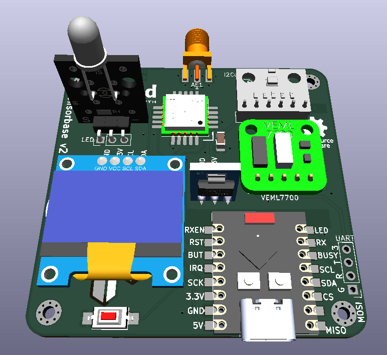
Check out the PCB files with Kicad 10
The interactive BOM webpage helps during assembly. You can mark components placed and check their exact types.
You will need PlatformIO to compile and install it.
Then you can get the upstream Meshtastic repo, that you should merge into the firmware folder, where our custom variant files already describe the board.
| Qty | Value | Footprint | References |
|---|---|---|---|
| 4 | MountingHole | MountingHole:MountingHole_2.2mm_M2_Pad_Via | H1, H2, H3, H4 |
| 1 | 10uF | Capacitor_SMD:C_1206_3216Metric_Pad1.33x1.80mm_HandSolder | C1 |
| 1 | AMS1117 | Connector_PinHeader_2.54mm:PinHeader_1x03_P2.54mm_Vertical | J1 |
| 1 | Antenna_Shield | Library:SMA_4mm_ali_EdgeMount | AE1 |
| 1 | BME280 | Connector_PinHeader_2.54mm:PinHeader_1x06_P2.54mm_Vertical | J4 |
| 1 | Display | Connector_PinHeader_2.54mm:PinHeader_1x04_P2.54mm_Vertical | J2 |
| 1 | E22-900MM22S | Library:E22-900MM22S | U3 |
| 1 | ESP32-C3_SUPERMINI_SMD | Library:MODULE_ESP32-C3_SUPERMINI | U2 |
| 1 | I2Cext | Connector_PinHeader_2.54mm:PinHeader_1x04_P2.54mm_Vertical | J6 |
| 1 | LED | Connector_PinHeader_2.54mm:PinHeader_1x03_P2.54mm_Vertical | J8 |
| 1 | LOGO | Library:hologo_combined | G*** |
| 1 | LOGO | Library:360logo_all_medium | G*** |
| 1 | SW_Push | Button_Switch_SMD:SW_SPST_CK_RS282G05A3 | SW1 |
| 1 | UART | Connector_PinHeader_2.54mm:PinHeader_1x04_P2.54mm_Vertical | J3 |
| 1 | VEML7700 | Connector_PinHeader_2.54mm:PinHeader_1x05_P2.54mm_Vertical | J5 |
The 18 most common of 22 parts.
acseka360/sws_lbn
The interactive BOM webpage helps during assembly. You can mark components placed and check their exact types.


Louisiana-State-Rocketry/FLCM0001-A03_PCB
PCB Files for the Eclipse 2 Flight Computer.


LucasCanete/GermanSmartknob
On the front side there is a ring of RGB Leds for user feedback and at its center a magnetic encoder. The magnetic encoder is key to detect the rotation's direction of the BLDC Motor, that in this project is used as an…

MuffinByteLabs/esp32s3-plant-monitor
Portfolio PCB: ESP32-S3 Wi-Fi plant monitor. 4-layer KiCad 10 design, fabricated and assembled at JLCPCB — schematic, reviews and the frozen manufacturing package all readable in-browser.


Th3Link/homeautomation
Components for a CAN-bus home-automation system: relay/rollershutter/ light/button/sensor nodes on a shared CAN bus, bridged to MQTT (and from there to openHAB or Home Assistant) by a gateway.
It measures 60 × 60 mm and has 2 copper layers, 1.6 mm thick.
22 parts, built around the E22-900MM22S, BME280, VEML7700-TT and AMS1117. The full list of its parts is on this page, with links to each part's symbol and footprint where PCBKit's library has them.
From the acseka360/sws_lsb repository on GitHub, at the commit this page was made from: the board is pcb/lora_board.kicad_pcb and its schematic pcb/lora_board.kicad_sch. PCBKit opens the board in the browser, with nothing to install.
Its repository states no licence, so its author keeps all rights: ask acseka360 before reusing the design.