2 layers81.2 × 81.2 mm

 LucasCanete/GermanSmartknob
On the front side there is a ring of RGB Leds for user feedback and at its center a magnetic encoder. The magnetic encoder is key to detect the rotation's direction of the BLDC Motor, that in this project is used as an…
SmartKnob Bachelorarbeit is an open-source printed circuit board by LucasCanete, from the LucasCanete/GermanSmartknob repository on GitHub. It is a 4-layer board of 71 × 71 mm with 111 parts on 95 nets, routed with 707 tracks and 307 vias.
It is built around the ESP32-S3-MINI-1-N8, SN65HVD230D and SN74LV1T34DBV, with the MT6701CT-STD, NAU8822L and TMC6300-LA among its other parts. Its parts include 44 capacitors, 21 resistors, 10 ICs, 9 diodes and 5 connectors. It belongs with the ESP32 boards of this library.


An ESP32-S3 based knob to control smart devices at home. Based on Scott Bez's Smartknob: https://github.com/scottbez1/smartknob?tab=readme-ov-file. Adapted for the standard german wall socket.
This project mechatronic project has three main parts. The first part consisted of the development of a PCB that could fit in the standard german wall socket and would control sensors, touch display and a BLDC Motor. The second part consisted on 3d printed pieces to sustain the PCB on its place, allow BLDC rotation while keeping the touch display on its place. Finally the third part was the software, which tested that all sensors and actuators worked accordingly. The final product can be seen below.
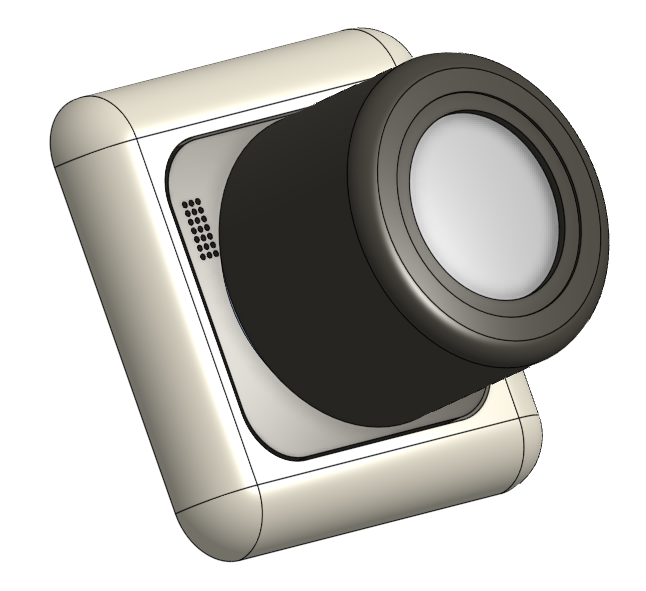
German Smartknob
A summarized description of this products three main parts.
The PCB was designed to fit into the standard german wall socket. It has two sides.
On the front side there is a ring of RGB Leds for user feedback and at its center a magnetic encoder. The magnetic encoder is key to detect the rotation's direction of the BLDC Motor, that in this project is used as an input device, similar to a rotary encoder. The reason why a BLDC Motor was chosen and not a regular rotary encoder, is because with the first, through proper driver, it is possible to program the motor's torque and adjust it according to the user's use. Besides of this, at the sides of the Front-PCB there are sensors to detect the temperature, the room's brightness and also output audio via a speaker.
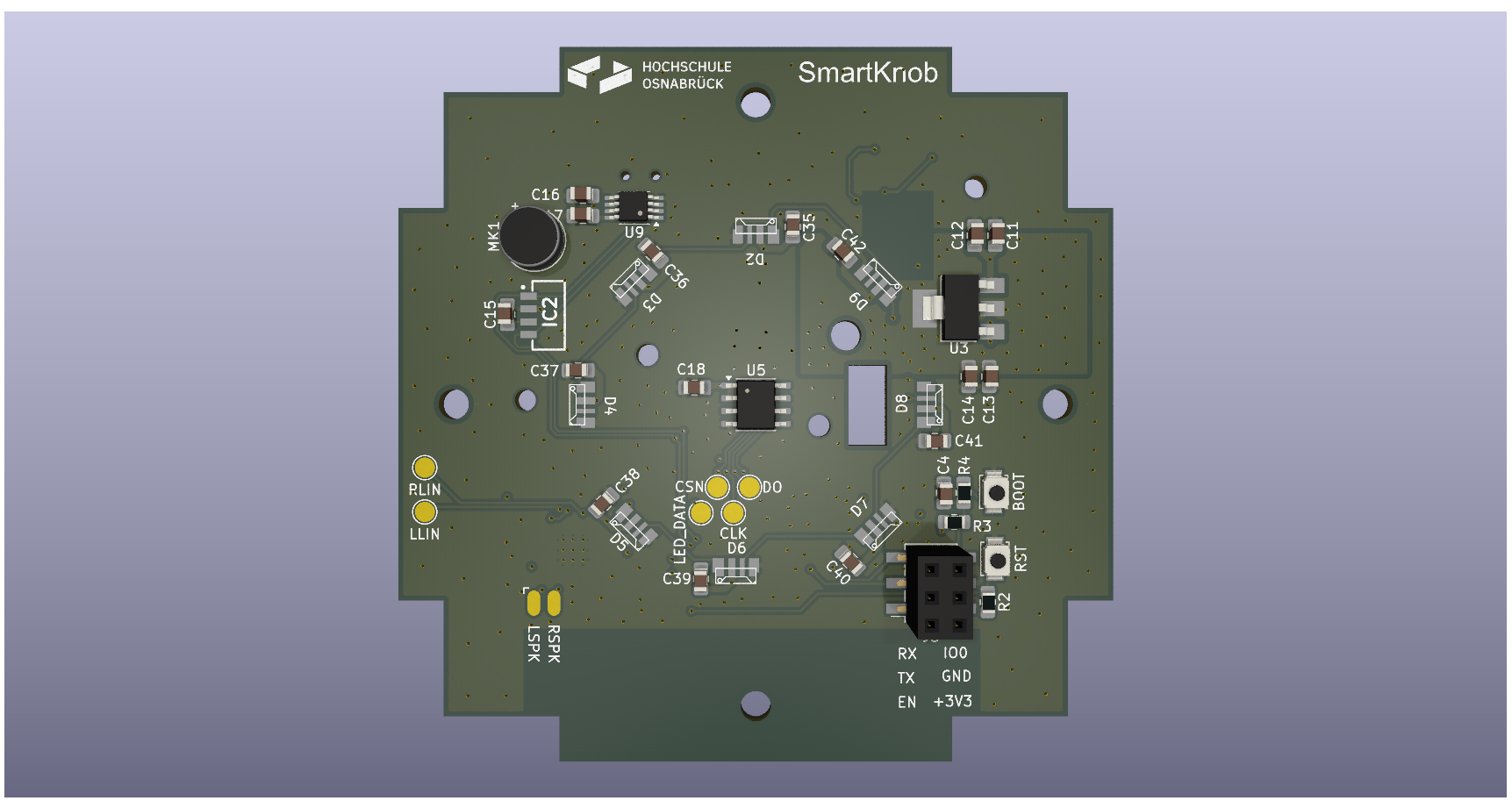
Figure 1: Front side PCB
On the back side there are connectors available to supply the PCB with 24V, 3.3v and extra outputs with I2C and CAN lines. The Display connector pads, the ESP32-S3, and the audio and bldc driver are also found on the back side of the PCB.
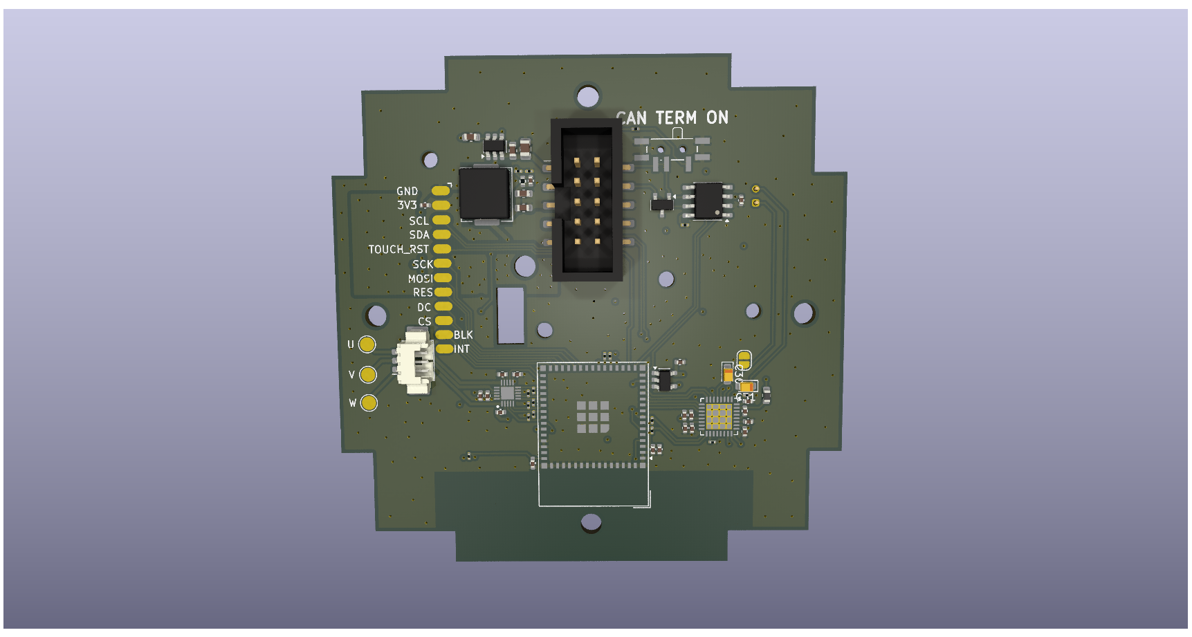
Figure 2: Backside PCB
Using the OnShape CAD tool several 3D pieces were designed, that later were 3d printed. The pieces include a holder for the BLDC Motor to keep it in the middle; a holder for the display, a knob and a case to hide the electronic. Below is an exploded view of the internal pieces of the smartknob.
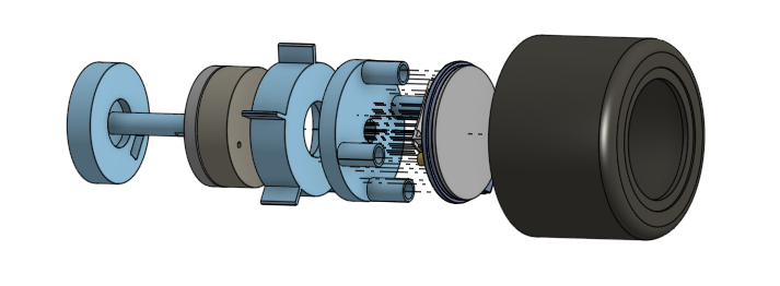
Figure 3: Internal Pieces
The software was built using the arduino libraries, for simplicities sake. The main goal of the software program was to demonstrate the correct functioning of the main features of the smartknob. Because of this, a small Manu was programmed in which 4 main features can be selected as options. With a tap on the touch display the option can be selected and the functioning of the feature can be demonstrated.
The four menu options and what each of them does is represented with the diagram below:
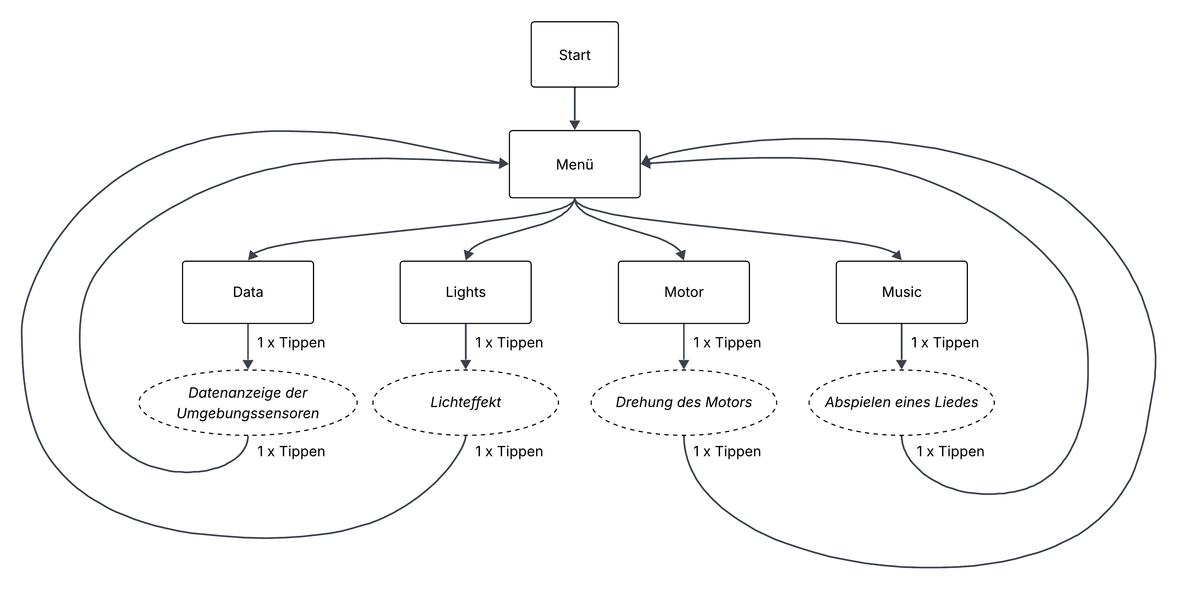
Figure 4: Software Diagram
git clone https://github.com/LucasCanete/GermanSmartknob.git


This project is still under development. Eventhough the first version was successful, improvements are still coming to the software side. Some of them are:
| Qty | Value | Footprint | References |
|---|---|---|---|
| 12 | 0.1uF | Capacitor_SMD:C_0805_2012Metric_Pad1.18x1.45mm_HandSolder | C4, C15, C17, C18, C35, C36, C37, C38, C39, C40, C41, C42 |
| 10 | 10K | Resistor_SMD:R_0201_0603Metric | R1, R6, R13, R14, R15, R16, R17, R18, R19, R22 |
| 8 | SK6812SIDE-A | liebler_OPTO:SK6812_SIDE_A_handsolder | D2, D3, D4, D5, D6, D7, D8, D9 |
| 7 | 0.1uF | Capacitor_SMD:C_0402_1005Metric | C1, C22, C23, C24, C26, C34, C43 |
| 6 | 4.7uF | Capacitor_SMD:C_0402_1005Metric | C25, C27, C28, C29, C32, C33 |
| 5 | 3K3 | Resistor_SMD:R_0201_0603Metric | R7, R9, R10, R11, R12 |
| 3 | MountingHole | MountingHole:MountingHole_2.2mm_M2 | H1, H2, H3 |
| 2 | 1uF | Capacitor_Tantalum_SMD:CP_EIA-2012-12_Kemet-R | C30, C31 |
| 2 | 1uF | Capacitor_SMD:C_0805_2012Metric_Pad1.18x1.45mm_HandSolder | C12, C14 |
| 2 | 22uF | Capacitor_SMD:C_0603_1608Metric | C9, C10 |
| 2 | 4.7uF | Capacitor_SMD:C_0805_2012Metric_Pad1.18x1.45mm_HandSolder | C11, C13 |
| 2 | MountingHole | MountingHole:MountingHole_2.1mm | H4, H4 |
| 1 | 0.1uF | Capacitor_SMD:C_0402_1005Metric_Pad0.74x0.62mm_HandSolder | C3 |
| 1 | 0.1uF/16V | Capacitor_SMD:C_0603_1608Metric | C7 |
| 1 | 0.1uF/35V | Capacitor_SMD:C_0603_1608Metric | C5 |
| 1 | 10K | Resistor_SMD:R_0805_2012Metric_Pad1.20x1.40mm_HandSolder | R3 |
| 1 | 10n/50V | Capacitor_SMD:C_0402_1005Metric | C19 |
| 1 | 10u | Inductor_SMD:L_APV_APH0630 | L1 |
| 1 | 10u | Capacitor_SMD:C_0402_1005Metric | C20 |
| 1 | 10uF | Capacitor_SMD:C_0402_1005Metric | C45 |
| 1 | 10uF | Capacitor_SMD:C_0805_2012Metric_Pad1.18x1.45mm_HandSolder | C16 |
| 1 | 10uF/35V | Capacitor_SMD:C_0805_2012Metric | C6 |
| 1 | 120 | Resistor_SMD:R_0201_0603Metric | R21 |
| 1 | 1K | Resistor_SMD:R_0805_2012Metric_Pad1.20x1.40mm_HandSolder | R4 |
| 1 | 1M | Resistor_SMD:R_0402_1005Metric | R5 |
| 1 | 22uF | Capacitor_SMD:C_0402_1005Metric | C2 |
| 1 | 2K2 | Resistor_SMD:R_0201_0603Metric | R20 |
| 1 | 56pF | Capacitor_SMD:C_0402_1005Metric | C8 |
| 1 | 600R | Inductor_SMD:L_0603_1608Metric | FB1 |
| 1 | AMS1117 | liebler_SEMICONDUCTORS:SOT-223-3_TabPin2_HANDSOLDER | U3 |
| 1 | BOOT | Button_Switch_SMD:SW_SPST_B3U-1000P | SW2 |
| 1 | BaseConnect | Connector_IDC:IDC-Header_2x05_P2.54mm_Vertical_SMD | J1 |
| 1 | CLK | TestPoint:TestPoint_Pad_D2.0mm | TP4 |
| 1 | CSN | TestPoint:TestPoint_Pad_D2.0mm | TP3 |
| 1 | Conn_01x12_Pin | SolderPads:SolderPads_2mm_12 | J4 |
| 1 | Conn_motor | Connector_Molex:Molex_PicoBlade_53261-0371_1x03-1MP_P1.25mm_Horizontal | J2 |
| 1 | DO | TestPoint:TestPoint_Pad_D2.0mm | TP5 |
| 1 | ESP32-S3-MINI-1 | RF_Module:ESP32-S2-MINI-1 | U1 |
| 1 | Jumper_2_Bridged | Jumper:SolderJumper-2_P1.3mm_Bridged2Bar_RoundedPad1.0x1.5mm | JP1 |
| 1 | K22 | Resistor_SMD:R_0805_2012Metric_Pad1.20x1.40mm_HandSolder | R2 |
| 1 | LED_DATA | TestPoint:TestPoint_Pad_D2.0mm | TP9 |
| 1 | LLIN | TestPoint:TestPoint_Pad_D2.0mm | TP1 |
| 1 | LOGO | pcb_images:hs_osna_5 | G*** |
| 1 | MCP9808_MSOP | Package_SO:MSOP-8_3x3mm_P0.65mm | U9 |
| 1 | MT6701CT | Package_SO:SO-8_3.9x4.9mm_P1.27mm | U5 |
| 1 | Microphone_Condenser | Sensor_Audio:POM-2244P-C3310-2-R | MK1 |
| 1 | NAU8822 | Package_DFN_QFN:QFN-32-1EP_5x5mm_P0.5mm_EP3.6x3.6mm_ThermalVias | U6 |
| 1 | NUP2105L | Package_TO_SOT_SMD:SOT-23 | D10 |
| 1 | PROG | Connector_PinHeader_1.27mm:PinHeader_2x03_P1.27mm_Vertical_SMD | J3 |
| 1 | RLIN | TestPoint:TestPoint_Pad_D2.0mm | TP2 |
| 1 | RST | Button_Switch_SMD:SW_SPST_B3U-1000P | SW1 |
| 1 | SN65HVD230 | Package_SO:SOIC-8_3.9x4.9mm_P1.27mm | U8 |
| 1 | SN74LV1T34DBV | Package_TO_SOT_SMD:SOT-23-5 | U7 |
| 1 | SW_SPDT_with_Case | liebler_MECH:SW_SPDT_PCM12_handsolder | SW3 |
| 1 | Speaker_out | SolderPads:SolderPads_2mm_2 | J5 |
| 1 | TMC6300-LA | TMC6300:QFN40P300X300X90-21N | IC1 |
| 1 | TPS54202DDC | Package_TO_SOT_SMD:SOT-23-6 | U2 |
| 1 | U | TestPoint:TestPoint_Pad_D2.0mm | TP7 |
| 1 | V | TestPoint:TestPoint_Pad_D2.0mm | TP8 |
| 1 | VEML7700-TT | VEML7700:VEML7700 | IC2 |
| 1 | W | TestPoint:TestPoint_Pad_D2.0mm | TP6 |
| 1 | u1 | Capacitor_SMD:C_0402_1005Metric | C21 |


klaus-liebler/sensact
Es gibt vier Namespaces für Nachrichten "REQUEST" und "RESPONSE", "EVENT" und "ACKNOWLEDGE". Dies wird mit den beiden LSB des Versions-Namespace-Bytes erklärt (Somit bleiben 64 Versionierungsmöglichkeiten) Alle vier…


KipJM/blackmacro-hardware
An open source, smaller, more configurable, and more capabable video editing keyboard based on the raspberry Pi Pico 2W.

sequoia-hope/dancing-forest-pcb
The PCB design for the Dancing Forest art project

jkramarz/TheTick
The Tick is the next evolution in covert access control system implants for simulating adversary-in-the-middle attacks.
It measures 71 × 71 mm and has 4 copper layers, 1.6 mm thick.
111 parts, built around the ESP32-S3-MINI-1-N8, SN65HVD230D, SN74LV1T34DBV and MT6701CT-STD. The full list of its parts is on this page, with links to each part's symbol and footprint where PCBKit's library has them.
From the LucasCanete/GermanSmartknob repository on GitHub, at the commit this page was made from: the board is Hardware/SmartKnob_V2/SmartKnob_Bachelorarbeit.kicad_pcb and its schematic Hardware/SmartKnob_V2/SmartKnob_Bachelorarbeit.kicad_sch. PCBKit opens the board in the browser, with nothing to install.
Its repository states no licence, so its author keeps all rights: ask LucasCanete before reusing the design.