Skip to the content
PCBKitNew board
2 layers77.5 × 48.5 mmE Ink Badge, the printed circuit board in 3D

Inspired by Github Universe 2024 badge

Size
77.5 × 48.5 mm
Copper layers
2
Thickness
1.6 mm
Parts
78
Nets
98
Pads
308
Tracks, vias
910, 77
Routed
Yes
KiCad
KiCad 10.0 (file 20260206)
Created
9 May 2026
Updated
4 Sep 2026

Overview

E Ink Badge is an open-source printed circuit board by Acidicts, from the Acidicts/E-Ink-Badge repository on GitHub. It is a 2-layer board of 77.5 × 48.5 mm with 78 parts on 98 nets, routed with 910 tracks and 77 vias.

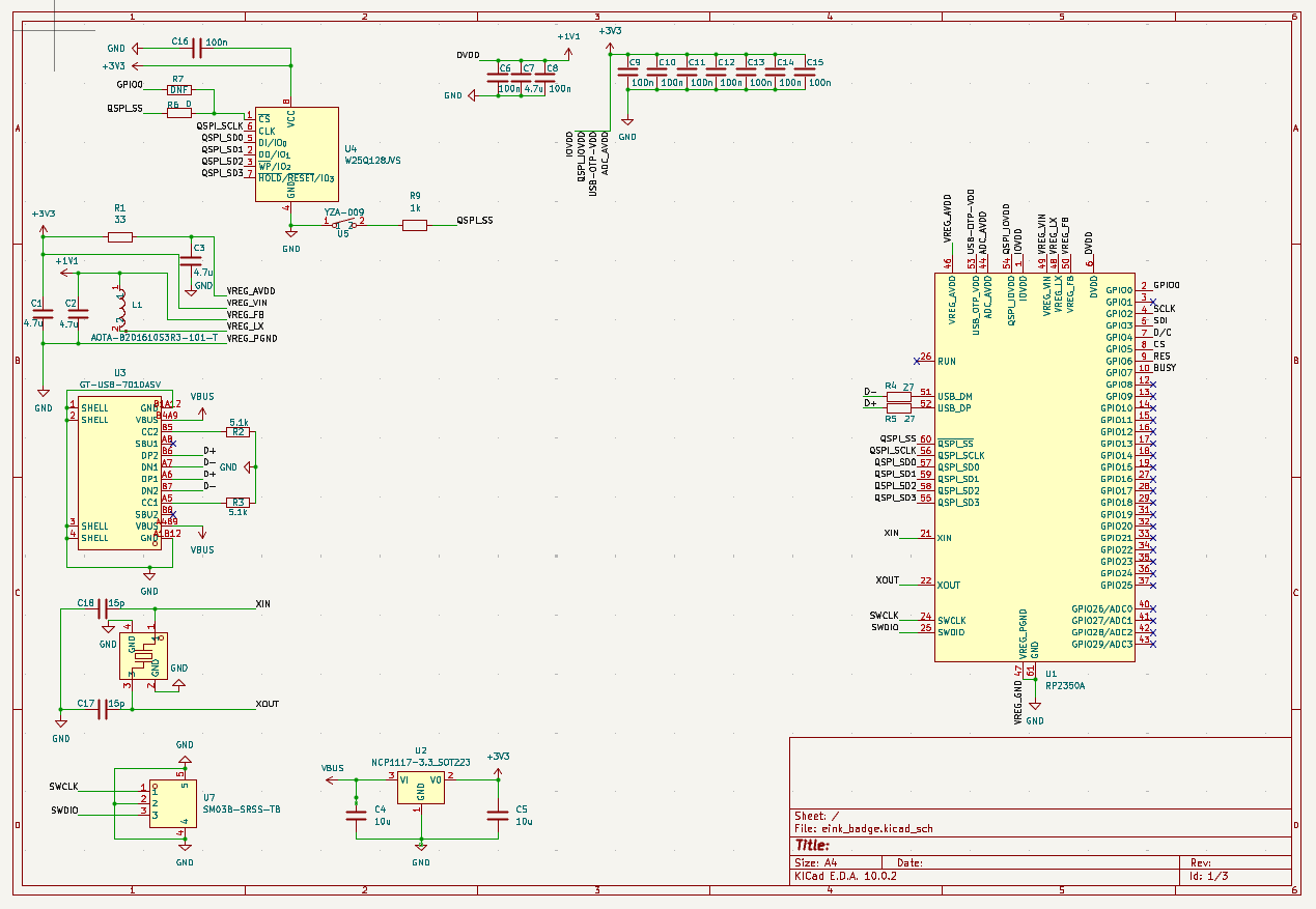
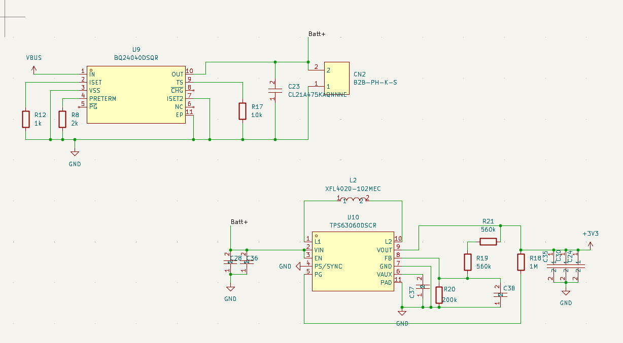
It is built around the RP2350A, TPS63060DSCR and W25Q128JVSIQ, with the ABM8-272-T3, BQ24040DSQR and CY43-10UH among its other parts. Its parts include 38 capacitors, 21 resistors, 10 ICs, 3 diodes and 2 inductors. It belongs with the lEDs and displays boards and the RP2350 boards of this library.

Main components

12

README

README.md

E-Ink Badge

A DIY Custom Designed, Monochrome, E-Ink display badge powered by the RP2350A, inspired by the GitHub Universe 2024 conference badge. ~Kinda wanted to see how many words I could describe it with.

E-Ink Badge render 1 E-Ink Badge render 2

(Renders made in Fusion 360)

Assembled badge, main view E-Ink display detail Battery mounting detail
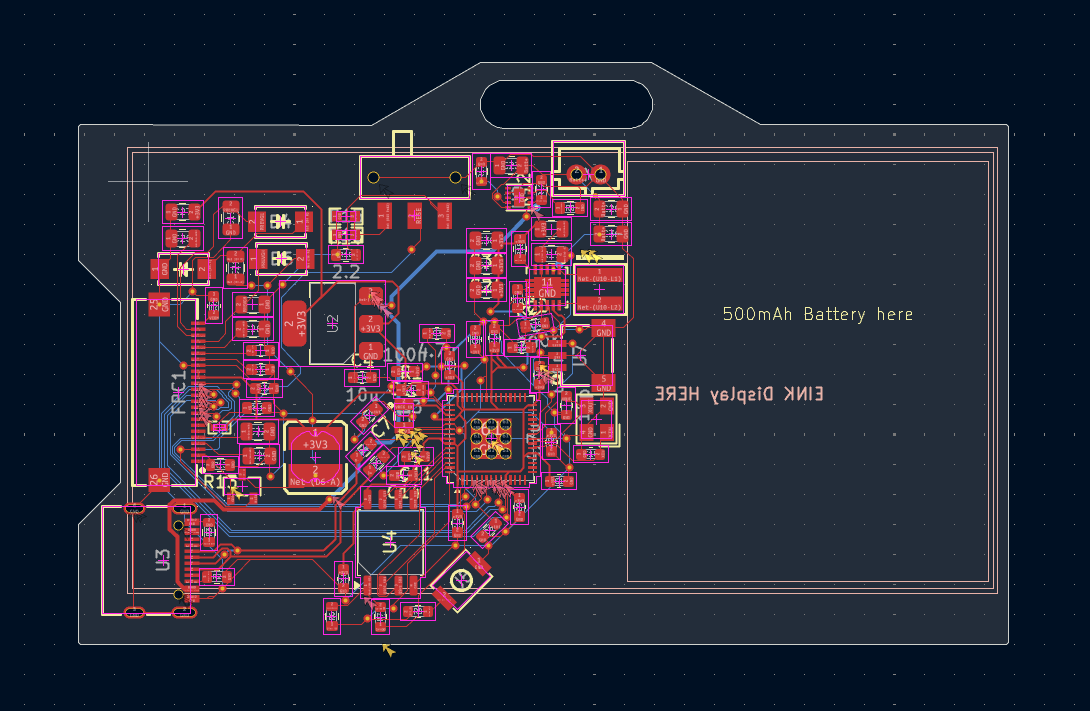
PCB layout

Features

  • MCU: The mighty RP2350A I wish the RP2354A were in stock though
  • Flash: 16MB onboard but do I want it to remember?
  • Power: Integrated battery management for a single-cell LiPo, does it charge idk
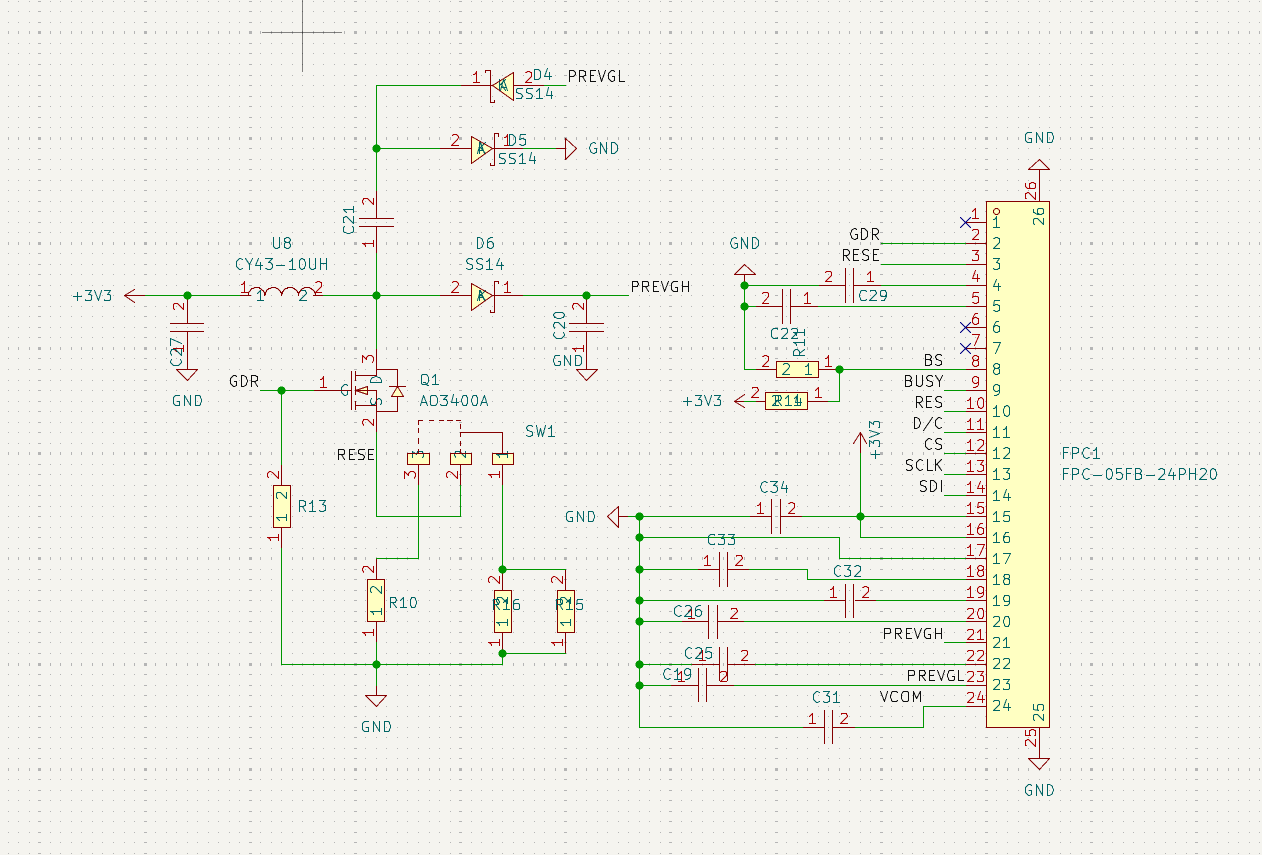
  • Display: E-Ink support over SPI, this was painful for part selection
  • Software: No dedicated firmware/software yet — I'm considering adapting the Badger 2040 software from the GitHub Universe conference badge as a starting point, don't have the time for it

Build Guide

This board has some fine-pitch and hand-soldering-unfriendly parts (the RP2350A and the E-Ink display's FPC connector), so I'd recommend using a PCBA service for the main board rather than hand-soldering it yourself. I know I wouldn't I have tried and failed, mainly cuz I dont have a hotplate.

Most components will already be populated(i liked this fancy word better than placed) by the assembly service — you'll only need to install the battery and the display yourself:

Bring your own adhesive, please ~ Not on BOM cuz not required for functionality

  1. Prepare the battery connector: Trim the battery connector's legs slightly so they don't press against the back of the display once everything is assembled.
  2. Mount the battery: Apply adhesive to the marked area on the PCB and stick the battery down.
  3. Connect the battery: Plug the battery cable into the battery connector on the PCB.
  4. Mount the display: Apply adhesive to the marked area on the front of the PCB and attach the E-Ink display.
  5. Connect the display cable: Route the ribbon cable through the indentation/slot in the PCB. Open the FPC connector's clamp arm, insert the ribbon cable, then press the clamp lever back down to lock it in place.

"That's it — the badge is fully assembled", I'd like to say, whether the firmware actually works, is what I'd like to know.

For getting started with software, I'd recommend flashing CircuitPython, as it's the easiest way to get up and running. Also have some demo firmware included in this repo, though it's untested/may not work out of the box.

Firmware

I have some basic firmware in this repo. If you'd like to write your own, here are the SPI pin mappings for the display connection:

SPI Pinout

SignalGPIO
SCLK (Clock)GPIO 2
SDI (MOSI/Data)GPIO 3
D/C (Data/Command)GPIO 4
CS (Chip Select)GPIO 5
RES (Reset)GPIO 6
BUSYGPIO 7

Bill of Materials (BOM)

  • Project BOM — full parts list for the badge
  • PCB BOM — parts list specific to the PCB assembly

AI Usage Declaration

  • In part research
  • Part finding (lcsc is hit or miss at finding stuff)
  • Firmware Demo creation
  • README Build Guide (code completion - fancy autocorrect ig)

Parts

78
QtyValueFootprintReferences
10100nCapacitor_SMD:C_0603_1608MetricC6, C8, C9, C10, C11, C12, C13, C14, C15, C16
9CL21A475KAQNNNECapacitor_SMD:C_0805_2012MetricC19, C20, C21, C22, C23, C25, C26, C27, C29
41uFCapacitor_SMD:C_0603_1608MetricC31, C32, C33, C34
44.7uCapacitor_SMD:C_0603_1608MetricC1, C2, C3, C7
322uFCapacitor_SMD:C_0805_2012MetricC24, C30, C35
3SS14easyeda2kicad:SMA_L4.2-W2.6-LS5.0-RD_1D4, D5, D6
21easyeda2kicad:R0603R15, R16
210kResistor_SMD:R_0603_1608MetricR13, R17
210uCapacitor_SMD:C_0603_1608MetricC4, C5
210uFCapacitor_SMD:C_0805_2012MetricC28, C36
215pCapacitor_SMD:C_0603_1608MetricC17, C18
21kResistor_SMD:R_0603_1608MetricR9, R12
22.2Resistor_SMD:R_0603_1608MetricR10, R11
227Resistor_SMD:R_0603_1608MetricR4, R5
25.1kResistor_SMD:R_0603_1608MetricR2, R3
2560kResistor_SMD:R_0805_2012MetricR19, R21
10Resistor_SMD:R_0603_1608MetricR6
10.1uFCapacitor_SMD:C_0603_1608MetricC37
110keasyeda2kicad:R0402R14
110pFCapacitor_SMD:C_0603_1608MetricC38
11MResistor_SMD:R_0603_1608MetricR18
1200kResistor_SMD:R_0603_1608MetricR20
12kResistor_SMD:R_0603_1608MetricR8
133Resistor_SMD:R_0603_1608MetricR1
1ABM8-272-T3_C20625731easyeda2kicad:CRYSTAL-SMD_4P-L3.2-W2.5-BLU6
1AO3400Aeasyeda2kicad:SOT-23-3_L2.9-W1.3-P1.90-LS2.4-BRQ1
1AOTA-B201610S3R3-101-Teasyeda2kicad:IND-SMD_L2.0-W1.6_AOTA-B201610S3R3-101-TL1
1B2B-PH-K-Seasyeda2kicad:CONN-TH_B2B-PH-K-SCN2
1BQ24040DSQReasyeda2kicad:WSON-10_L2.0-W2.0-P0.40-BL-EPU9
1CY43-10UHeasyeda2kicad:IND-SMD_L4.5-W4.0U8
1DNFResistor_SMD:R_0603_1608MetricR7
1FPC-05FB-24PH20easyeda2kicad:FPC-SMD_24P-P0.50_FPC-05FB-24PH20FPC1
1GT-USB-7010ASVeasyeda2kicad:USB-C-SMD_G-SWITCH_GT-USB-7010ASVU3
1MST-12D18G2 SMD SLIDE SWITCHeasyeda2kicad:SW-SMD_3P-L9.1-W3.5-P2.50_MST-12D18G2SW1
1NCP1117-3.3_SOT223Package_TO_SOT_SMD:SOT-223-3_TabPin2U2
1RP2350APackage_DFN_QFN:QFN-60-1EP_7x7mm_P0.4mm_EP3.4x3.4mmU1
1SM03B-SRSS-TBeasyeda2kicad:CONN-SMD_SM03B-SRSS-TB-LF-SN-PU7
1TPS63060DSCReasyeda2kicad:WSON-10_L3.0-W3.0-P0.50-BL-EP-AU10
1W25Q128JVSPackage_SO:SOIC-8_5.3x5.3mm_P1.27mmU4
1XFL4020-102MECeasyeda2kicad:IND-SMD_L4.0-W4.0_XFL4020-102MEBL2
1YZA-009easyeda2kicad:SW-SMD_YZA-009U5

Questions

How big is the E Ink Badge PCB?

It measures 77.5 × 48.5 mm and has 2 copper layers, 1.6 mm thick.

What parts does the E Ink Badge use?

78 parts, built around the RP2350A, TPS63060DSCR, W25Q128JVSIQ and ABM8-272-T3. The full list of its parts is on this page, with links to each part's symbol and footprint where PCBKit's library has them.

Where can I download the E Ink Badge KiCad files?

From the Acidicts/E-Ink-Badge repository on GitHub, at the commit this page was made from: the board is kicad/eink_badge.kicad_pcb and its schematic kicad/battery_charger.kicad_sch. PCBKit opens the board in the browser, with nothing to install.

Can I use the E Ink Badge design in my own project?

Its repository states no licence, so its author keeps all rights: ask Acidicts before reusing the design.

Similar boards

  • 4 layers101 × 51.5 mmQuack core, the printed circuit board in 3D

    Quack core

    HeyPCB/quack-core

    Brain board for the Open Duck Mini: Pi Zero 2W carrier, 14-servo STS bus, fused 2S power path in stitched copper zones (15-18 A battery side), USB-C charging with balancing, IMU.

    138 parts1CERN-OHL-S-2.0
  • 2 layers100 × 100 mmG7 Senior Design V2, the printed circuit board in 3D

    G7 Senior Design V2

    Fugate-A/ChairGuru

    ChairGuru - A project mainly designed for classroom teachers but has applications in all areas concerning chair management! We have designed a chair system that allows an end-user to create a layout from their computer…

    53 parts
  • 4 layers60 × 60 mmUmmon, the printed circuit board in 3D

    Ummon

    JonaWe/ummon

    ummon (from German Umgebungsmonitor, "environment monitor") is an ESP32-C6 based environmental sensor board with USB-C power.

    95 parts
  • 4 layers32.4 × 40.2 mmSmartwatch, the printed circuit board in 3D

    Smartwatch

    Pedro-Seixas/Smartwatch

    A custom-designed smartwatch built around the ESP32-S3, combining BLE connectivity, a rectangular touch display, recharge capability, IMU and temperature sensors. Designed from the ground up in KiCad.

    55 partsMIT
  • 4 layers154 × 81 mmSystem candidate, the printed circuit board in 3D

    System candidate

    bernardopg/ps28-modern-amp

    Infinity Primus PS28 amplifier modernization: TPA3255 engineering, validation and safety-gated workflow

    269 parts1
  • 2 layers128.2 × 61 mmMoistureiq PCB, the printed circuit board in 3D

    Moistureiq PCB

    tdarcher/moistureiq_PCB

    109 parts
  • 2 layers35 × 45 mmAether, the printed circuit board in 3D

    Aether

    EnriqueNeyra/aether

    All-in-one home air quality monitor measuring Temp, Humidity, CO2, VOCs, Particulate Matter, and NOx. Powered by ESP32-C3 running esphome, and built with Home Assistant integration

    57 parts129
  • 2 layers69.4 × 113 mmEpaper reader hw, the printed circuit board in 3D

    Epaper reader hw

    mathias4833/epaper-reader-hw

    An open-source e-paper reader

    126 parts75CERN-OHL-W-2.0