


2 layers98 × 83.8 mm
Projeto placa
phfbertoleti/placa_lorawan
Repositório oficial da placa LoRaWAN, um kit de desenvolvimento para protótipos IoT.
39 parts19MIT
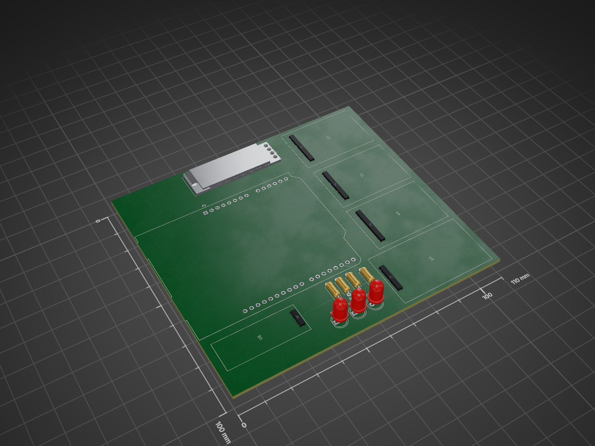
 aarthirethinabala/Air-Pollution-Monitoring-System
PCB design for an Arduino-based air pollution and vehicle exhaust monitoring system using multiple gas sensors, temperature/humidity sensing, an OLED display, LEDs and an alarm
Air pollution is an open-source printed circuit board by aarthirethinabala, from the aarthirethinabala/Air-Pollution-Monitoring-System repository on GitHub. It is a 2-layer board of 110 × 100 mm with 14 parts on 38 nets, routed with 61 tracks and 0 vias.
It is built around the ARDUINO UNO R3, DHT22 and MQ-2. Its parts include 6 ICs, 4 resistors and 3 diodes. It belongs with the lEDs and displays boards and the AVR (ATmega, ATtiny) boards of this library.
An Arduino-based air pollution and vehicle exhaust monitoring system designed to detect multiple gases and environmental conditions using gas sensors and a temperature/humidity sensor.
PCB Design Completed
This project is designed to monitor air pollution using using multiple gas sensors connected to an Arduino Uno. The system uses gas sensors to detect different pollutants and provides visual and audible indications based on the detected conditions. Temperature and humidity are also monitored, and the readings can be displayed using an OLED display. The PCB was designed as a controller and interface board, with the sensor modules connected externally through the provided connections.
The PCB was developed through the following stages:
The completed PCB contains the Arduino interface connections, sensor connections, display connection, indicator LEDs, buzzer, and supporting circuitory. The external sensor modules are connected to the PCB through their respective headers.
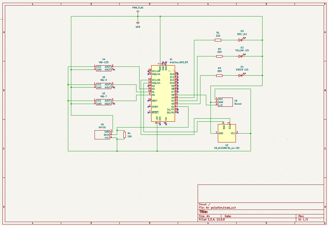
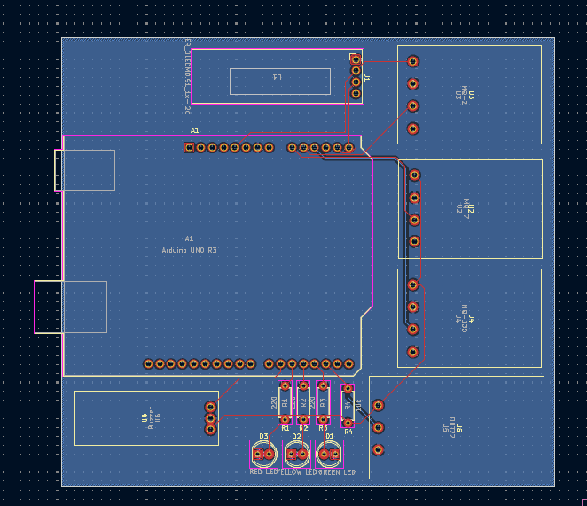
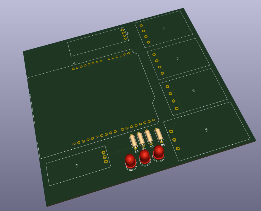
| Qty | Value | Footprint | References |
|---|---|---|---|
| 3 | 220 | Resistor_THT:R_Axial_DIN0207_L6.3mm_D2.5mm_P7.62mm_Horizontal | R1, R2, R3 |
| 1 | 10k | Resistor_THT:R_Axial_DIN0207_L6.3mm_D2.5mm_P7.62mm_Horizontal | R4 |
| 1 | Arduino_UNO_R3 | Module:Arduino_UNO_R3 | A1 |
| 1 | Buzzer | Vehicle Exhaust:Buzzer Module | U6 |
| 1 | DHT22 | Vehicle Exhaust:DHT22 | U5 |
| 1 | ER_OLEDM0.91_1x-I2C | Display:ER_OLEDM0.91_1x-I2C | U1 |
| 1 | GREEN LED | LED_THT:LED_D5.0mm | D1 |
| 1 | MQ-135 | Vehicle Exhaust:MQ-135 | U4 |
| 1 | MQ-2 | Vehicle Exhaust:MQ-2 | U3 |
| 1 | MQ-7 | Vehicle Exhaust:MQ-7 | U2 |
| 1 | RED LED | LED_THT:LED_D5.0mm | D3 |
| 1 | YELLOW LED | LED_THT:LED_D5.0mm | D2 |
phfbertoleti/placa_lorawan
Repositório oficial da placa LoRaWAN, um kit de desenvolvimento para protótipos IoT.


ajaiseelan333-cpu/ai-rescue-rover
Low-cost tracked scout rover for disaster zones. It enters a collapsed or smoke-filled structure before rescuers and sends back live video, person-detection alerts, and gas and temperature readings.

aleksul/WeatherStation
If you want a customizable solution for monitoring weather in your town, you're in the right place!


frodegill/airsensor
PCB and Arduino code for custom air quality sensor

javiermunoz2/office-digital-twin-iot
Office digital twin: ESP32 sensor node (custom KiCad PCB) → ThingsBoard → n8n → PostgreSQL, with a live web dashboard and an LLM assistant

Mohanalakshmi06/KiCAD_Railshield
This file contains all the details of the Schematic view of our Project.
It measures 110 × 100 mm and has 2 copper layers, 1.6 mm thick.
14 parts, built around the ARDUINO UNO R3, DHT22 and MQ-2. The full list of its parts is on this page, with links to each part's symbol and footprint where PCBKit's library has them.
From the aarthirethinabala/Air-Pollution-Monitoring-System repository on GitHub, at the commit this page was made from: the board is Air pollution.kicad_pcb and its schematic Air pollution.kicad_sch. PCBKit opens the board in the browser, with nothing to install.
Its repository states no licence, so its author keeps all rights: ask aarthirethinabala before reusing the design.