2 layers
 ZeroPhone/ZeroPhone-Mod-PCBs12
ZeroPhone mod board PCB files
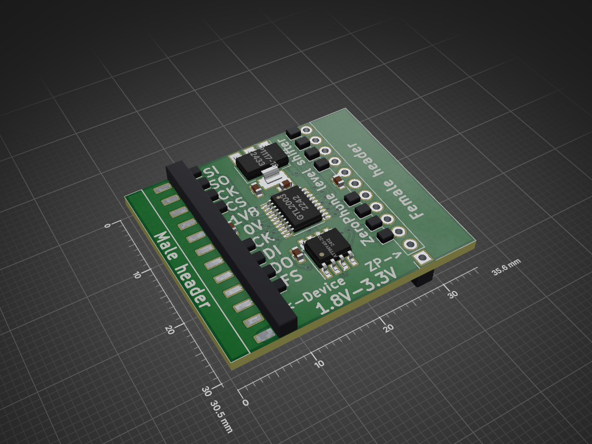
Level shifter adapter is an open-source printed circuit board by ZeroPhone, from the ZeroPhone/ZeroPhone-Mod-PCBs repository on GitHub, published under the GPL-3.0 licence. It is a 2-layer board of 35.6 × 30.5 mm with 45 parts on 35 nets, routed with 436 tracks and 37 vias.
It is built around the ATTINY45-20SU, BC847 and IRLML6401, with the BAV70 among its other parts. Its parts include 6 capacitors, 6 resistors, 5 transistors, 3 ICs and 2 diodes. It belongs with the interfaces and adapters boards and the AVR (ATmega, ATtiny) boards of this library.


ZeroPhone mod board PCB files
| Qty | Value | Footprint | References |
|---|---|---|---|
| 16 | J | footprints:GS2_SMALL | JP1, JP2, JP3, JP4, JP5, JP6, JP7, JP8, JP9, JP10, JP11, JP12, JP13, JP14, JP15, JP16 |
| 6 | 100nF | Capacitors_SMD:C_0603 | C1, C2, C3, C4, C5, C6 |
| 5 | 10K | Resistors_SMD:R_Array_Convex_4x0603 | RN1, RN2, RN3, RN4, RN5 |
| 3 | 1K | Resistors_SMD:R_0603 | R2, R3, R8 |
| 3 | BC847 | TO_SOT_Packages_SMD:SOT-23 | Q1, Q3, Q5 |
| 2 | 10K | Resistors_SMD:R_0603 | R4, R5 |
| 2 | Conn_01x12 | lib:Pin_Header_Combined_1x12_Pitch2.54mm | J1, J2 |
| 2 | IRLML6401 | TO_SOT_Packages_SMD:SOT-23 | Q2, Q4 |
| 1 | 100K | Resistors_SMD:R_0603 | R1 |
| 1 | AP1117-18 | TO_SOT_Packages_SMD:SOT-223-3_TabPin2 | U2 |
| 1 | ATTINY45-20SU | Housings_SOIC:SOIC-8_3.9x4.9mm_Pitch1.27mm | U3 |
| 1 | BAV70 | TO_SOT_Packages_SMD:SOT-23 | D1 |
| 1 | GTL2003 | Housings_SSOP:SSOP-20_4.4x6.5mm_Pitch0.65mm | U1 |
| 1 | LED | LEDs:LED_0805 | D2 |


UzixLS/mist1010-board
10x10cm PCB variant of MIST FPGA project for G738/G706 enclosure

Petezah/roomba_wall_v2
An AVR program for ATTiny85 to transmit a virtual wall signal for an iRobot Roomba


cbs-ntcore/cbs_badge
This badge is designed to highlight digital fabrication techniques that are commonly used in the Neurotechnology Core(NTCore) at the Center for Brain Science at Harvard University.

enwi/PiSupply
Uninterruptable power supply for Raspberry Pi's, which can also power external HDDs

mar0x/bike_motor_shim
Shimano e-bike shim between wheel sensor and motor to "extend the limits"
It measures 35.6 × 30.5 mm and has 2 copper layers, 1.6 mm thick.
45 parts, built around the ATTINY45-20SU, BC847, IRLML6401 and BAV70. The full list of its parts is on this page, with links to each part's symbol and footprint where PCBKit's library has them.
From the ZeroPhone/ZeroPhone-Mod-PCBs repository on GitHub, at the commit this page was made from: the board is level_shifter_adapter/level_shifter_adapter.kicad_pcb. PCBKit opens the board in the browser, with nothing to install.
Its repository publishes it under the GPL-3.0 licence: you may reuse it on that licence's terms (keep the author's notice, and for a copyleft licence share your changes alike).