2 layers300 × 100 mm

 ZIZO932/Terraskipper-V2
Terraskipper is a project about building a mudskipper-inspired soft robot that can help in agriculture. The robot is designed to move on difficult surfaces like mud and uneven land while using sensors and soft robotics technology to support smart farming and environmental monitoring.
Terraskipper is an open-source printed circuit board by ZIZO932, from the ZIZO932/Terraskipper-V2 repository on GitHub. It is a 2-layer board of 51 × 85 mm with 24 parts on 49 nets, routed with 158 tracks and 0 vias.
It is built around the BTS7960B, DS18B20 and HC-SR04, with the RASPBERRY PI PICO 2W among its other parts. Its parts include 9 connectors, 4 ICs, 2 capacitors and 1 resistor. It belongs with the robots and motor control and sensors and measurement boards and the RP2040 and RP2350 boards of this library.


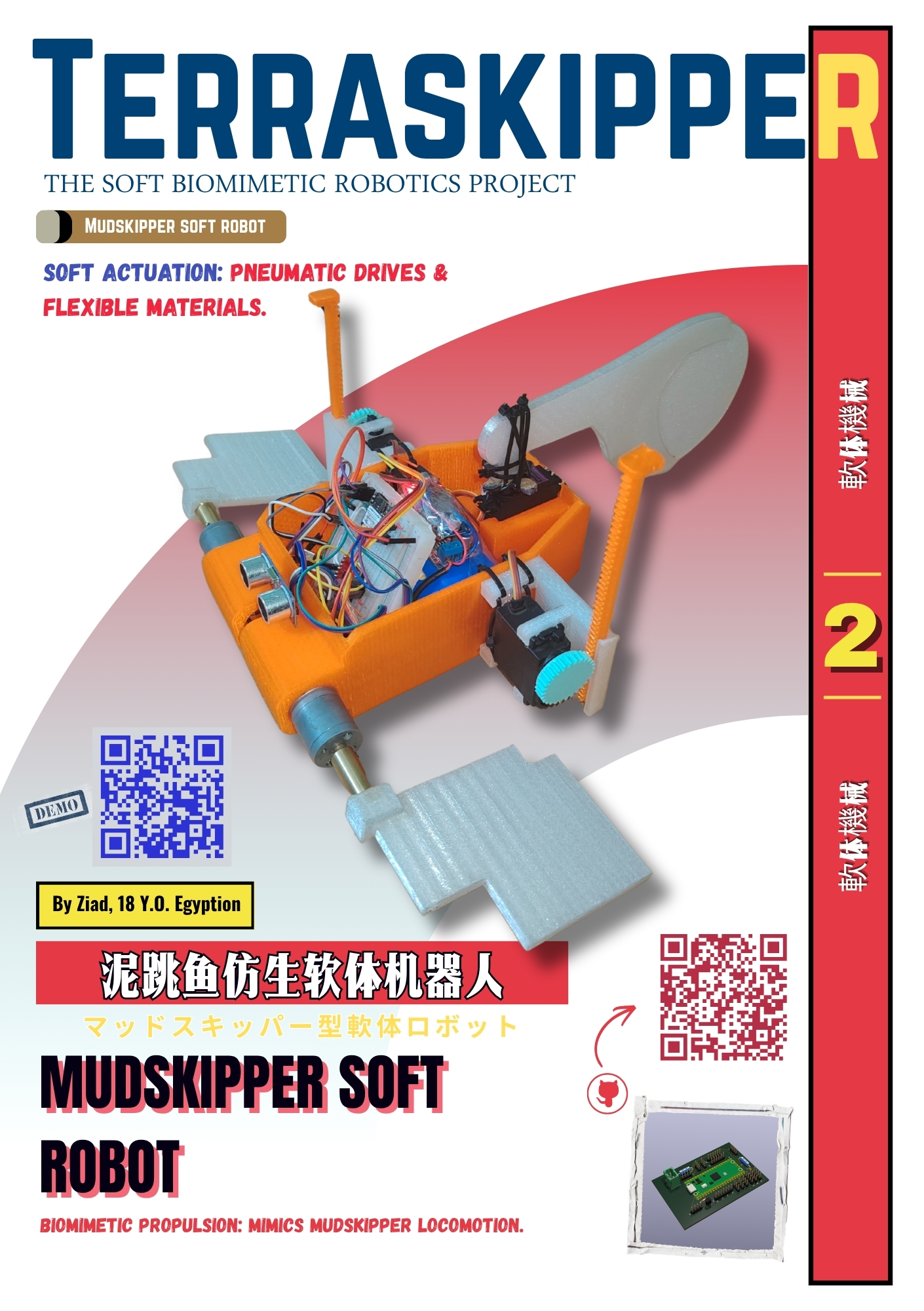
A mudskipper-inspired robot I've been building to explore soil monitoring on difficult ground. This version moves the pectoral fins with DC geared motors, uses servos for the tail and sensor placement, and runs on a Raspberry Pi Pico 2 W.
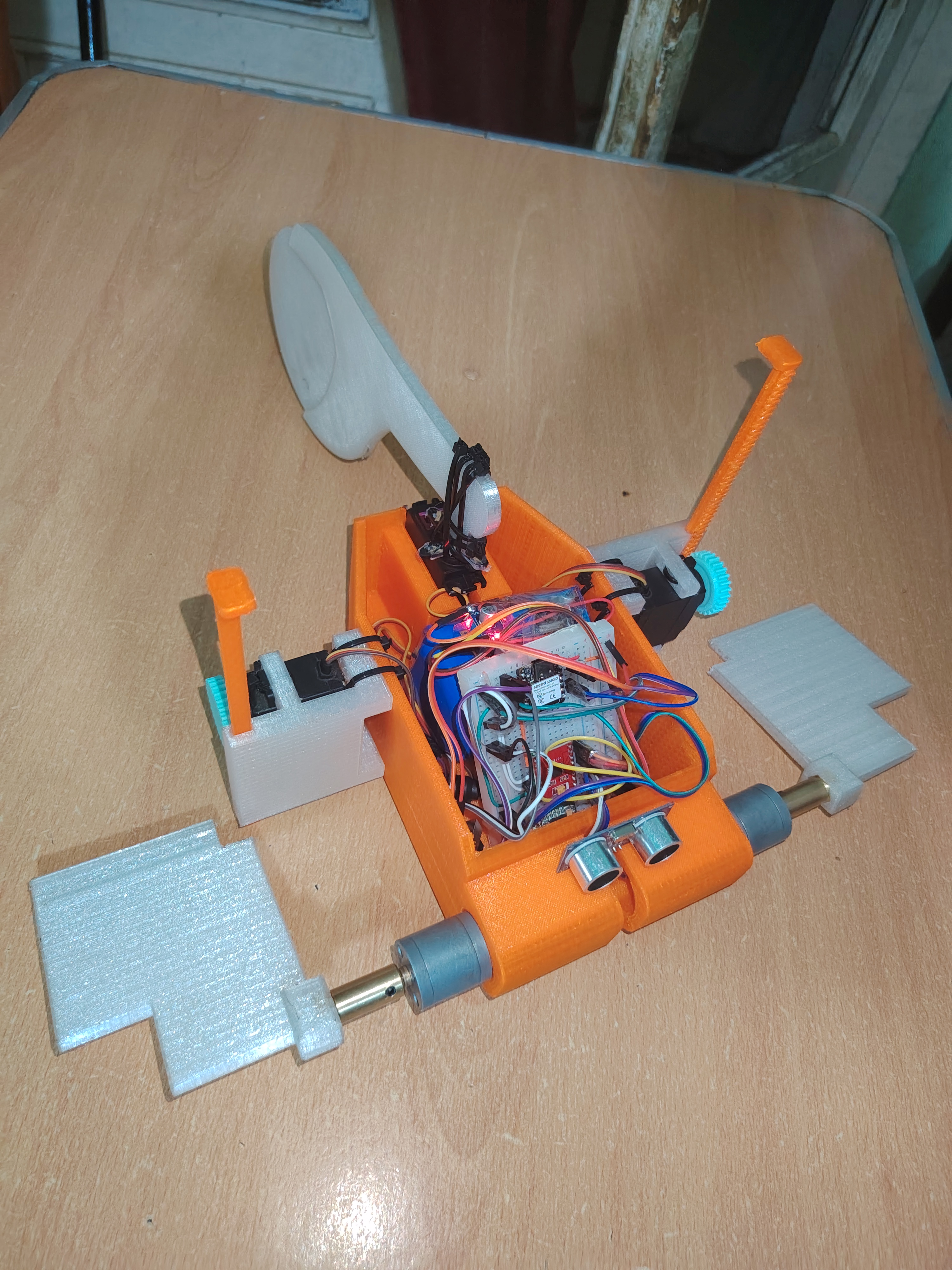
The project started with soil problems in Egypt's Nile Delta. I wanted to explore a robot that could carry sensors over muddy ground, and the way a mudskipper moves between land and water gave me an idea for the mechanism.
This repo documents the prototype, its design files, and the changes I made while building it. The main things I worked on here were movement, fitting the electronics inside the body, and getting sensor readings from the assembled robot.
I replaced the front servos with DC geared motors for more torque. I also redesigned the body, added proper PCB mounting, and made the sensor placement mechanism detachable so I could work on it without taking the whole robot apart.
After the first assembly, I reprinted the body at a smaller size. Everything still had to fit inside, so I checked the alignment again and adjusted the parts where needed. The smaller body used less filament and reduced the weight.
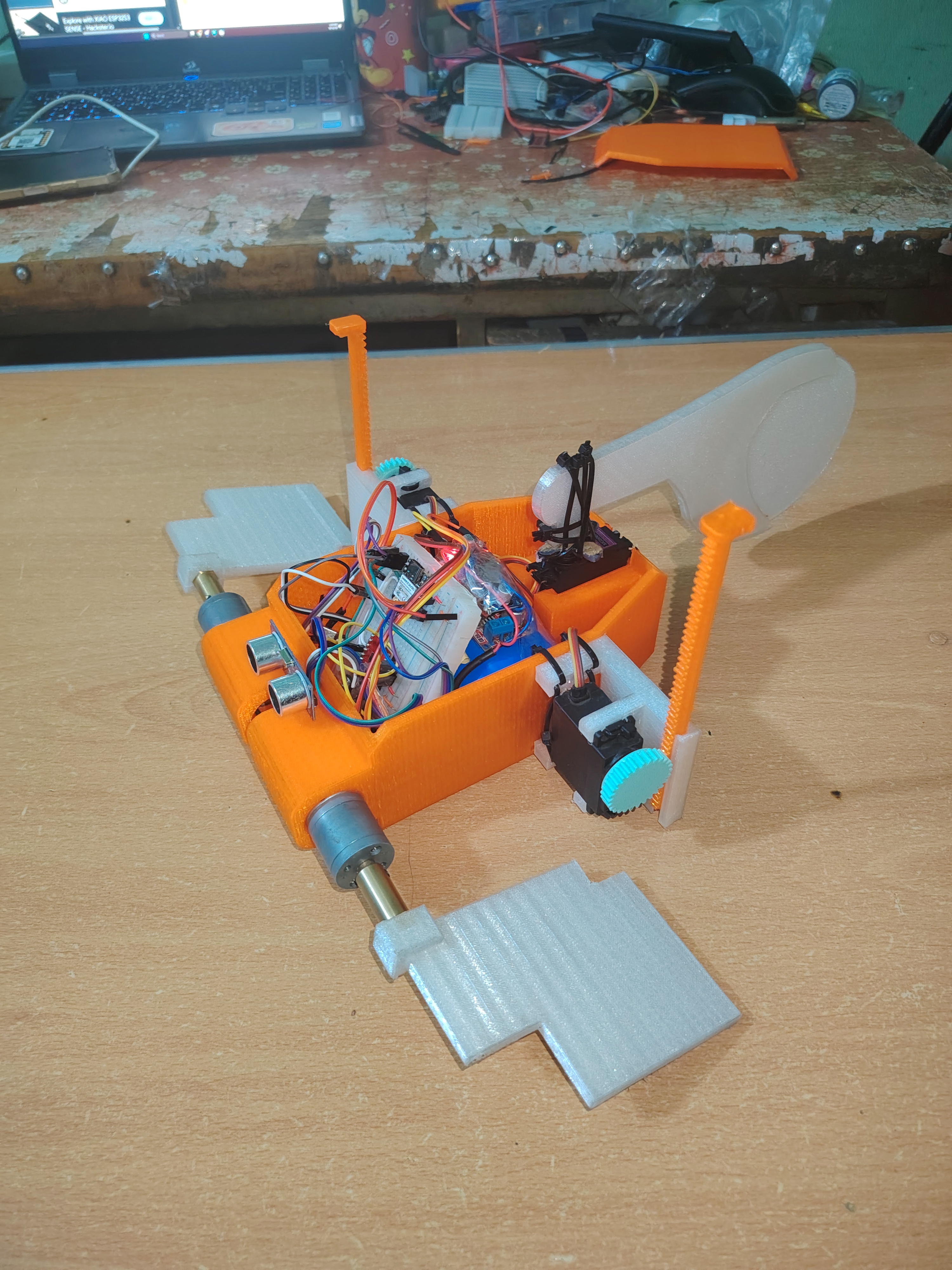
The motor model changed during the build: my movement notes list JGB37-520 motors, while the original BOM lists JGA25-370 motors. The BOM below records the original estimate.
Firmware/Main.py drives the DC motors forward, sets the servos, reads the ultrasonic sensors and IMU, and prints temperature, moisture, and TDS telemetry. It starts the motors when run.
It's a movement and sensor test program. Autonomous navigation and pH measurement aren't implemented in this file, and the moisture and TDS conversions still depend on calibration for the actual sensors and test conditions.
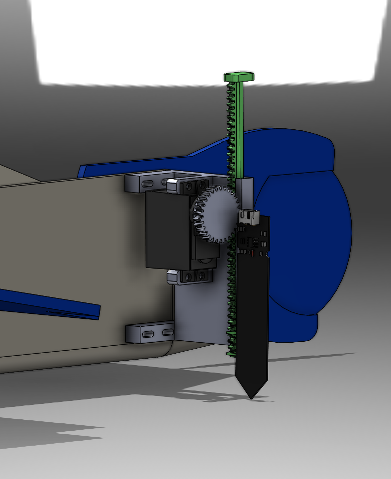
I used fillets and chamfers around the body edges, and designed a small vertical slider to lower the sensors toward the soil. The mechanism can be removed separately for repairs.
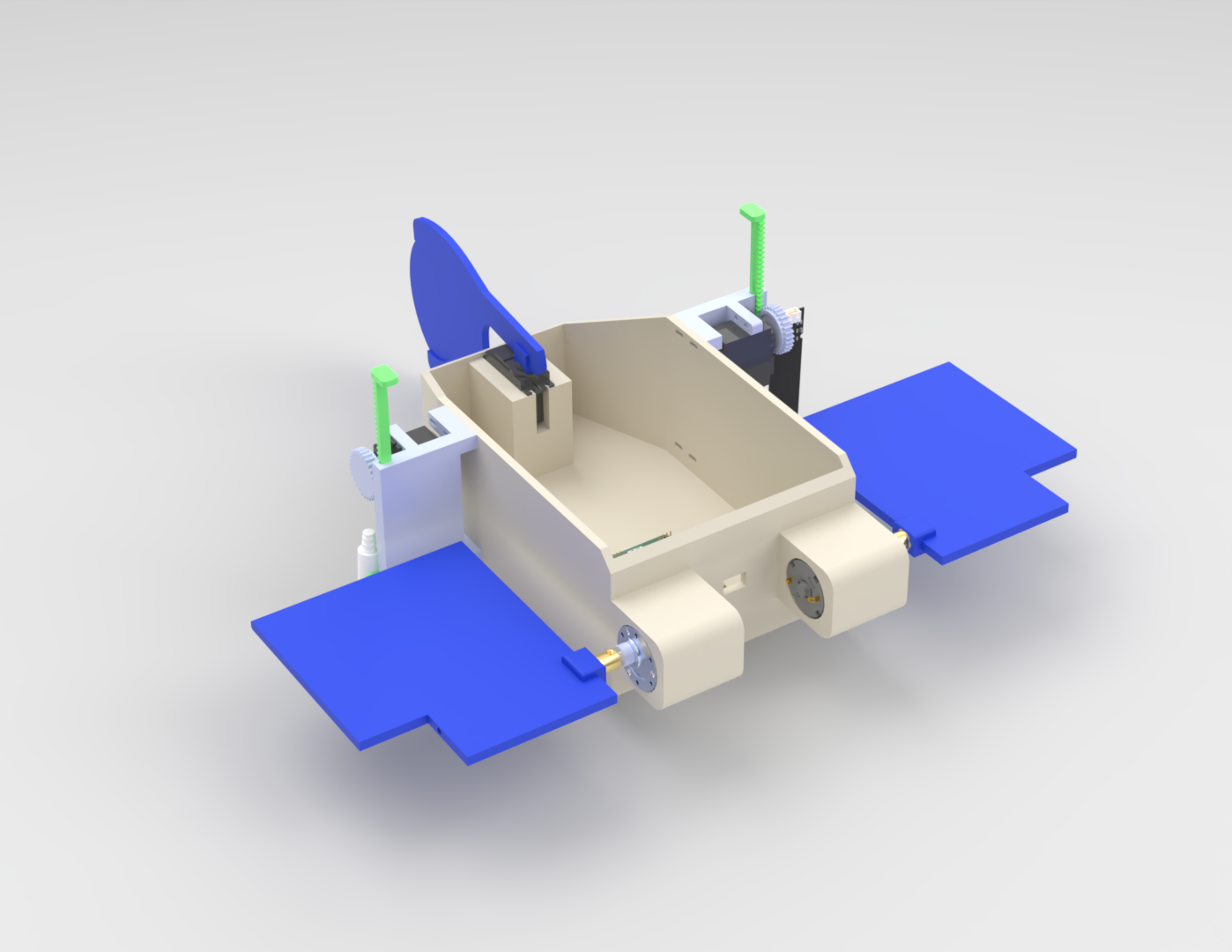
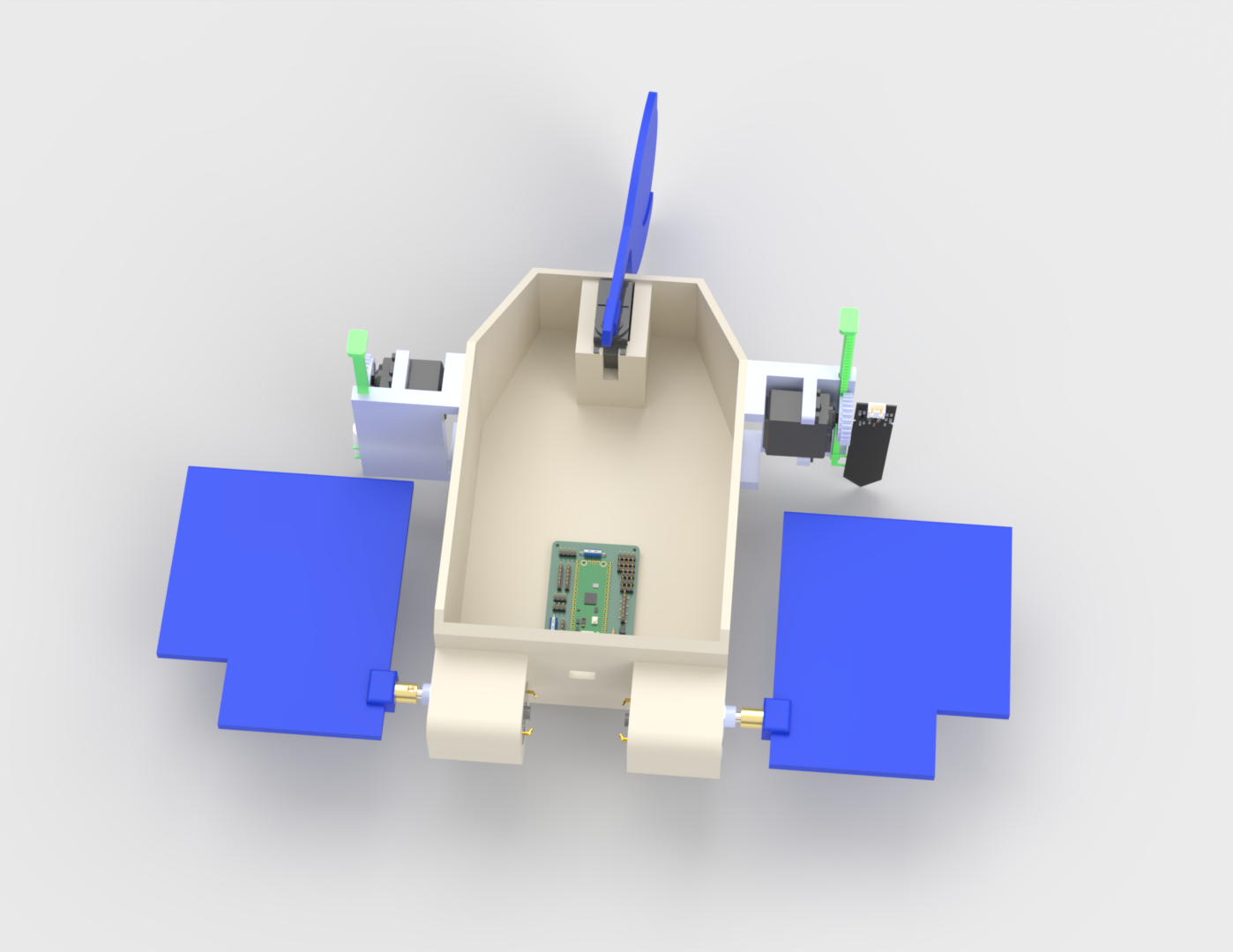
The custom board has two layers, with signals and power routing on top and a ground plane underneath. The design includes two BTS7960 motor drivers and buck converters for the power rails.
I originally considered an ESP32, then switched to the Pico 2 W because I was more comfortable working in MicroPython. The current KiCad schematic and firmware use the Pico 2 W.
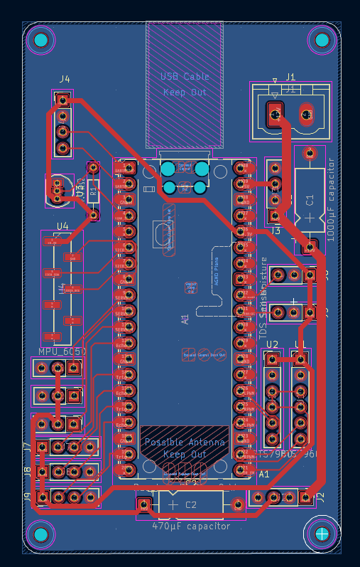
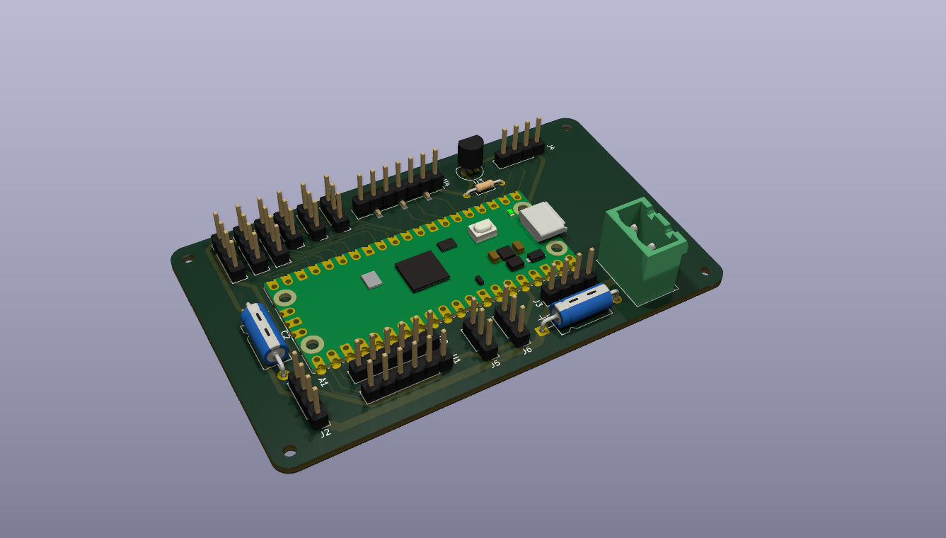
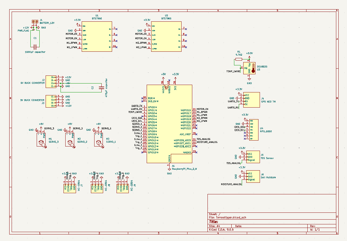
I rebuilt the circuit one section at a time: power first, then the controller, then the sensors. PCB review also caught missing mounting details, layout changes, and gaps in the CAD and Gerber files.
One of the more frustrating faults was the right motor refusing to move. I swapped the motors to check whether the motor itself was bad, then traced the problem back to the driver's motor B output and fixed it. After assembly I checked the wiring and ran the movement tests again before filming.
The recorded estimate is about 5,315 EGP, or $102.50 at the time. It covers the 18 items counted in the original BOM, with the build changes noted above. TDS is present in the schematic and firmware but isn't itemized in this BOM.
| Component | Category | Qty | Unit Price (EGP) | Total (EGP) |
|---|---|---|---|---|
| Raspberry pi Pico 2w | Microcontroller | 1 | 900 | 900 |
| BTS7960 43A DC Motor Driver | Motor Driver | 2 | 450 | 900 |
| MG996R 360° Servo Motor | Motors | 3 | 210 | 630 |
| DC Motor With Gear Box JGA25-370 12V 33RPM 30Kg.cm | Motors | 2 | 300 | 600 |
| Ublox NEO-7M GPS Module | Sensors | 1 | 540 | 540 |
| MPU-6050 IMU Gyro/Accel Module | Sensors | 1 | 175 | 175 |
| Capacitive Soil Moisture Sensor V2.0 | Sensors | 1 | 100 | 100 |
| DS18B20 Waterproof Temp Sensor | Sensors | 1 | 85 | 85 |
| HC-SR04 Ultrasonic Sensor | Sensors | 3 | 40 | 120 |
| Rechargeable Li-ion Battery Pack 18650 12V 6000mAh | Power | 1 | 900 | 900 |
| XL4016 8A Step-Down Buck Converter | Power | 1 | 243 | 243 |
| LM2596 3A Step-Down Buck Converter | Power | 1 | 122 | 122 |
| Total | 18 | 5,315 EGP |
Earlier stages are in TerraSkipper and Mudskipper.
Build notes by Ziad, as part of the TerraSkipper project.
| Qty | Value | Footprint | References |
|---|---|---|---|
| 4 | MountingHole | MountingHole:MountingHole_2.1mm | H1, H2, H3, H4 |
| 3 | HC-SR04 | Connector_PinHeader_2.54mm:PinHeader_1x04_P2.54mm_Vertical | J7, J8, J9 |
| 2 | BTS7960 | Connector_PinHeader_2.54mm:PinHeader_1x06_P2.54mm_Vertical | U1, U2 |
| 1 | 1000µF capacitor | Capacitor_THT:CP_Axial_L10.0mm_D4.5mm_P15.00mm_Horizontal | C1 |
| 1 | 4.7kΩ | Resistor_THT:R_Axial_DIN0204_L3.6mm_D1.6mm_P7.62mm_Horizontal | R1 |
| 1 | 470µF capacitor | Capacitor_THT:CP_Axial_L10.0mm_D4.5mm_P15.00mm_Horizontal | C2 |
| 1 | 5V BUCK CONVERTER | Connector_PinHeader_2.54mm:PinHeader_1x04_P2.54mm_Vertical | J3 |
| 1 | 6V BUCK CONVERTER | Connector_PinHeader_2.54mm:PinHeader_1x04_P2.54mm_Vertical | J2 |
| 1 | BATTERY_12V | Connector_Phoenix_MSTB:PhoenixContact_MSTBVA_2,5_2-G-5,08_1x02_P5.08mm_Vertical | J1 |
| 1 | DS18B20 | Package_TO_SOT_THT:TO-92_Inline | U3 |
| 1 | GPS NEO 7M | Connector_PinHeader_2.54mm:PinHeader_1x04_P2.54mm_Vertical | J4 |
| 1 | MPU_6050 | Connector_PinHeader_2.54mm:PinHeader_1x07_P2.54mm_Vertical_SMD_Pin1Left | U4 |
| 1 | RaspberryPi_Pico_2_W | Module:RaspberryPi_Pico_Common_Unspecified | A1 |
| 1 | SERVO_1 | Connector_PinHeader_2.54mm:PinHeader_1x03_P2.54mm_Vertical | M3 |
| 1 | SERVO_2 | Connector_PinHeader_2.54mm:PinHeader_1x03_P2.54mm_Vertical | M2 |
| 1 | SERVO_3 | Connector_PinHeader_2.54mm:PinHeader_1x03_P2.54mm_Vertical | M1 |
| 1 | Soil Moisture | Connector_PinHeader_2.54mm:PinHeader_1x03_P2.54mm_Vertical | J6 |
| 1 | TDS Sensor | Connector_PinHeader_2.54mm:PinHeader_1x03_P2.54mm_Vertical | J5 |


fnc765/aki300yenLCD-raspico2w
Raspberry Pi Pico 2 W (RP2350) で秋月電子の 300 円 LCD LTA042B010F (400×96 RGB666 TFT) を PIO + DMA で駆動し、その表示を持ったファームウェアを Wi-Fi 経由 (GitHub Release) で自己更新する リファレンス実装です。nostd の Rust と Embassy で書かれています。

gemarcano/wifi_pc_power_switch
Wireless enabled power switch for desktop PCs.


ChefsSlaad/PCBs_and_Micropython
storing custom pcbs and micropython code for home projects

liebrandapps/RPI-Multi-Purpose-Extension-Board
Kicad files for a printed circuit board extending the Raspberry Interfaces GPIOs.
It measures 51 × 85 mm and has 2 copper layers, 1.6 mm thick.
24 parts, built around the BTS7960B, DS18B20, HC-SR04 and RASPBERRY PI PICO 2W. The full list of its parts is on this page, with links to each part's symbol and footprint where PCBKit's library has them.
From the ZIZO932/Terraskipper-V2 repository on GitHub, at the commit this page was made from: the board is Schematic & PCB/Terraskipper.kicad_pcb and its schematic Schematic & PCB/Terraskipper.kicad_sch. PCBKit opens the board in the browser, with nothing to install.
Its repository states no licence, so its author keeps all rights: ask ZIZO932 before reusing the design.