2 layers21.7 × 10 mm
Sensor Unit
Dooganar/engg3800-t3-eaar-pcb-design
A repo used to track and collaborate on the pcb design for the University of Queensland "Team Project II" course.
164 parts

 Yoda-Flash/chord-board
A MIDI controller to experiment with chords, with all sorts of customization!
Chord board is an open-source printed circuit board by Yoda-Flash, from the Yoda-Flash/chord-board repository on GitHub. It is a 2-layer board of 137.7 × 134.7 mm with 90 parts on 112 nets, routed with 746 tracks and 98 vias.
It is built around the PAM8403DR-H, GPTS203211B and 74HC595D, with the CD74HC4067M96, DFR0847 and PTV09A-4020U-B103 among its other parts. Its parts include 26 capacitors, 20 diodes, 10 switches, 8 resistors and 7 ICs. It belongs with the ESP32 and RISC-V boards of this library.


The Chord Board is a MIDI controller, specifically designed for one to experiment with chords! Each note you play can be customized and looped.
I came up with this idea because I've always loved playing with different chords. I thought it would be cool to be able to experiment with them without having an actual instrument with me, or needing to learn the chords and fingerings to hear different combinations.
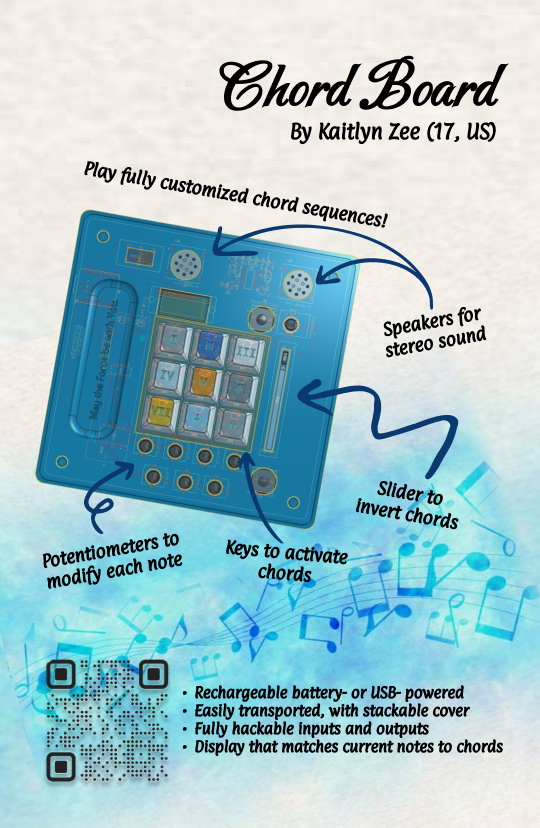
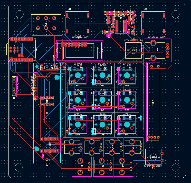
Top view:
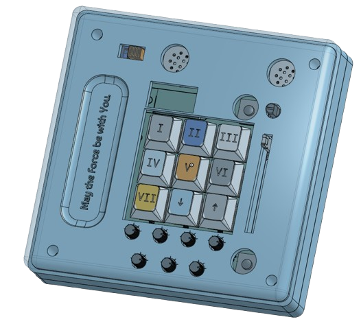
Bottom view:
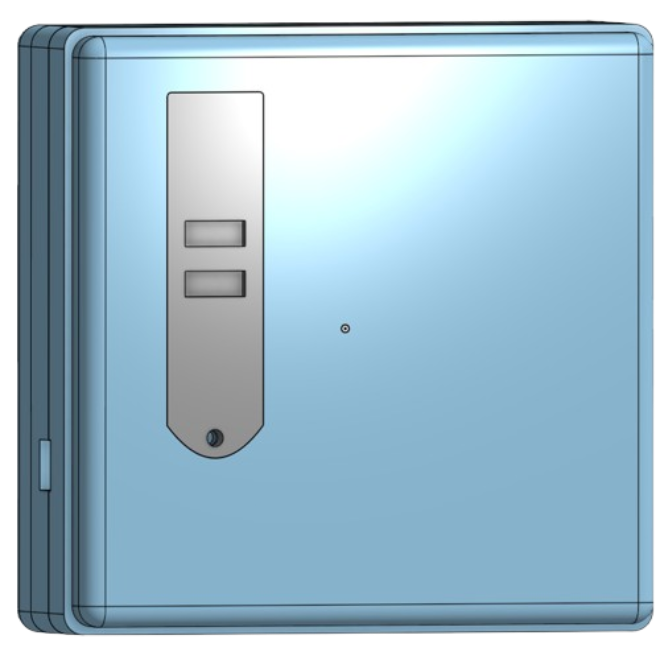
CAD of PCB with parts:
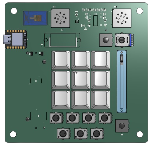
PCB:
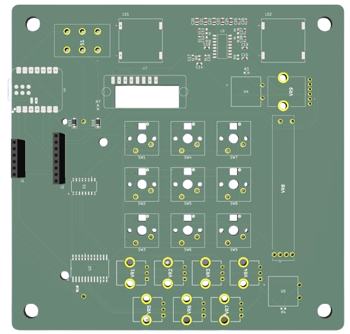
3D PCB Front:
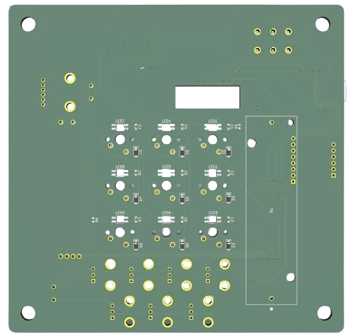
3D PCB Back:
Gather the assembled PCB and the 3D printed pieces in the cad folder, as well as 4 sets of M3 12mm screws and heat inserts and 1 set of M2 3mm screws and heat inserts.
Use a soldering iron to set the heat inserts in their respective holes (M2 3mm into the bottom case's back holes for the battery cover and M3 12mm for the bottom case's top holes for PCB mounting). Then, place the PCB in between the top and bottom case, and a battery and its cover into the slot on the back. Use a 2mm hex key to screw in the M2 screws and a 3mm hex key for the M3 one.
The firmware uses Circuit Python, so get started with it following https://learn.adafruit.com/welcome-to-circuitpython/installing-circuitpython
Within the Circuit Python drive,
use pip to install the requirements in requirements.txt and transfer the files from ./firmware to use!
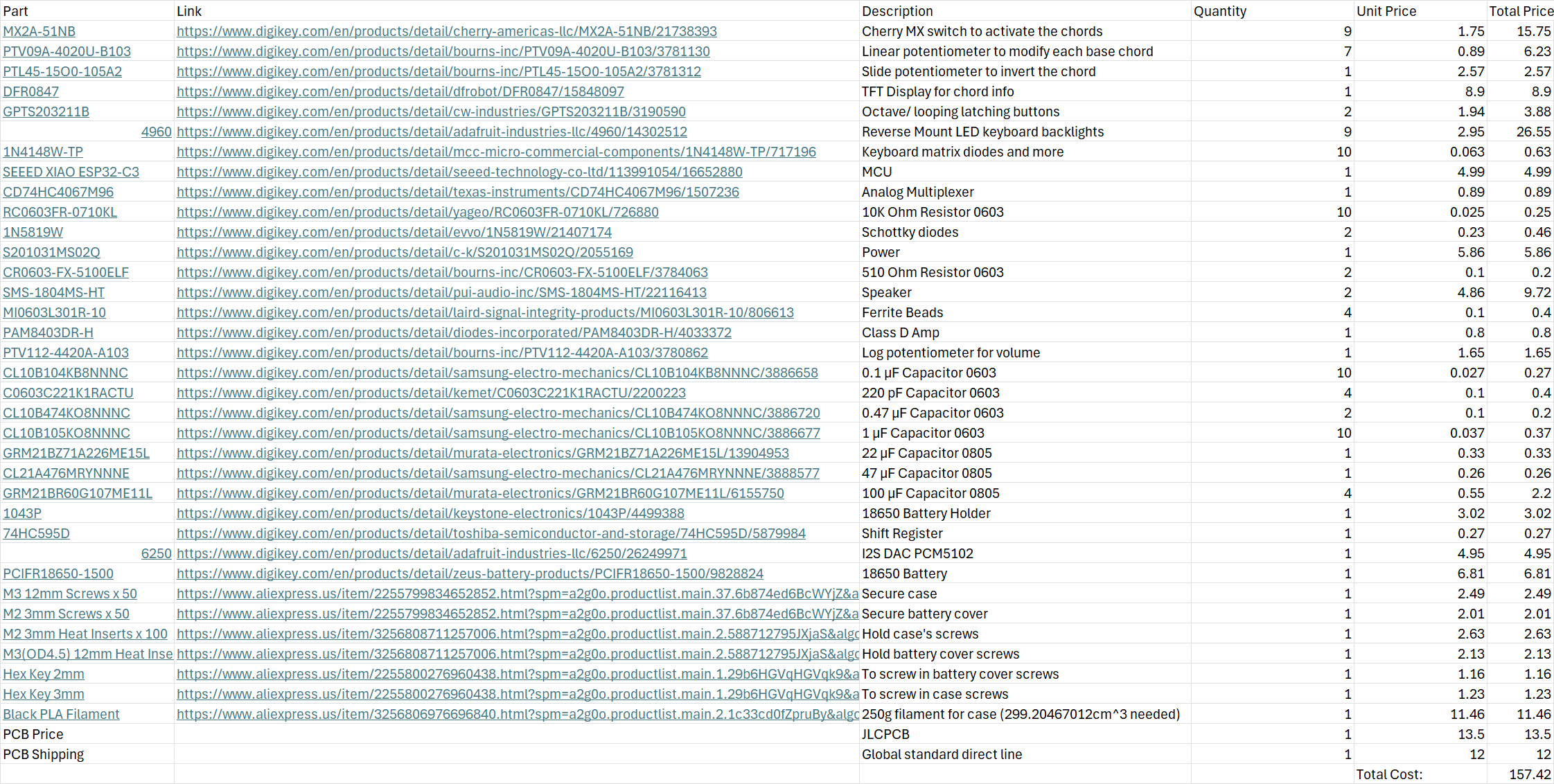
| Qty | Value | Footprint | References |
|---|---|---|---|
| 10 | 0.1 µF | Capacitor_SMD:C_0603_1608Metric | C1, C2, C3, C4, C5, C6, C7, C8, C9, C16 |
| 9 | 1N4148 | Diode_SMD:D_SOD-123 | D1, D2, D3, D4, D5, D6, D7, D8, D9 |
| 9 | SK6812-E 4960 | chord-board:SK6812-E 4960_ADA | LED1, LED2, LED3, LED4, LED5, LED6, LED7, LED8, LED9 |
| 9 | SW_SPST | Button_Switch_Keyboard:SW_Cherry_MX_1.00u_PCB | SW1, SW2, SW3, SW4, SW5, SW6, SW7, SW8, SW9 |
| 7 | PTV09A-4020U-B103 | chord-board:PTV09A4020UB103 | VR1, VR2, VR3, VR4, VR5, VR6, VR7 |
| 4 | 1 µF | Capacitor_SMD:C_0603_1608Metric | C17, C18, C19, C25 |
| 4 | 100 µF | Capacitor_SMD:C_0805_2012Metric | C20, C21, C22, C23 |
| 4 | 220 pF | Capacitor_SMD:C_0603_1608Metric | C11, C12, C27, C28 |
| 4 | MI0603L301R-10 | chord-board:FB_MI0603L301R-10 | E1, E2, E3, E4 |
| 3 | 510 Ω | chord-board:BO_CR0603 510 Ohms | R5, R6, R7 |
| 2 | 0.47 µF | Capacitor_SMD:C_0603_1608Metric | C14, C15 |
| 2 | 1N5819 | Diode_SMD:D_SOD-123F | D10, D11 |
| 2 | 20 kΩ | chord-board:BO_CR0603 510 Ohms | R8, R9 |
| 2 | GPTS203211B | chord-board:SWITCH_03211B | U4, U5 |
| 2 | RC0603FR-0710KL | chord-board:RC0603N_YAG | R3, R4 |
| 2 | SMS-1804MS-HT | chord-board:SPKR_SMS-1804MS-HT | LS1, LS2 |
| 1 | 10 kΩ | chord-board:RC0603N_YAG | R10 |
| 1 | 22 µF | Capacitor_SMD:C_0603_1608Metric | C26 |
| 1 | 3.7V 1043P | chord-board:BATT_1043P_KEY | B1 |
| 1 | 47 µF | Capacitor_SMD:C_0805_2012Metric | C24 |
| 1 | 74HC595D | chord-board:SOIC16_TOS | U1 |
| 1 | CD74HC4067M96 | chord-board:CD74HC4067M96 DW24 | U2 |
| 1 | Conn_01x06_Socket | Connector_PinSocket_2.54mm:PinSocket_1x06_P2.54mm_Vertical | J1 |
| 1 | Conn_01x08_Socket | Connector_PinSocket_2.54mm:PinSocket_1x08_P2.54mm_Vertical | J2 |
| 1 | DFR0847 | chord-board:DFR0874 SMD | U7 |
| 1 | NetTie_2 | NetTie:NetTie-2_SMD_Pad0.5mm | NT1 |
| 1 | PAM8403DR-H | chord-board:PAM8403DR-H | U8 |
| 1 | PTL45-15O0-105A2 | chord-board:PTL4515O0105A2 | VR8 |
| 1 | PTV112-4420A-A103 | chord-board:PTV1124420AA103 | VR9 |
| 1 | S201031MS02Q | chord-board:S201031MS02Q | S1 |
| 1 | XIAO-ESP32-C3 | chord-board:XIAO-ESP32-C3-SMD | U6 |
Dooganar/engg3800-t3-eaar-pcb-design
A repo used to track and collaborate on the pcb design for the University of Queensland "Team Project II" course.


constancegdl/RP2350-FI-Attack-PCB
PCB designed for fault injection on the RP2350.

deebot/MorphWatch-STM32
The Repo contains KiCAD hardware files and software for Morph Watch
It measures 137.7 × 134.7 mm and has 2 copper layers, 1.6 mm thick.
90 parts, built around the PAM8403DR-H, GPTS203211B, 74HC595D and CD74HC4067M96. The full list of its parts is on this page, with links to each part's symbol and footprint where PCBKit's library has them.
From the Yoda-Flash/chord-board repository on GitHub, at the commit this page was made from: the board is pcb/chord-board.kicad_pcb and its schematic pcb/chord-board.kicad_sch. PCBKit opens the board in the browser, with nothing to install.
Its repository states no licence, so its author keeps all rights: ask Yoda-Flash before reusing the design.