2 layers73.5 × 92.8 mm

 X-zeed/UTAC-PCB2
4-channel smart relay control board with ESP32-C3 SuperMini - KiCad PCB Design v0.2.0
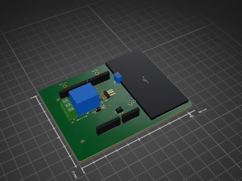
UTAC PCB is an open-source printed circuit board by X-zeed, from the X-zeed/UTAC-PCB repository on GitHub. It is a 2-layer board of 104 × 60 mm with 59 parts on 52 nets, routed with 444 tracks and 5 vias.
It is built around the HLK-10M05, MMBT2222A and MRA4003T3G-MS, with the SRA-05VDC-CL among its other parts. Its parts include 19 resistors, 11 connectors, 9 diodes, 8 capacitors and 4 transistors. It belongs with the home automation and IoT boards and the ESP32 and RISC-V boards of this library.


4-Channel Smart Relay Control Board powered by ESP32-C3 SuperMini with onboard AC–DC power supply.
UTAC PCB is a compact, mains-powered relay control board designed for home automation and industrial switching applications. It features four independently controllable relay channels driven by an ESP32-C3 SuperMini, enabling Wi-Fi and Bluetooth control without an external power adapter.
| Attribute | Value |
|---|---|
| Version | 0.2.0 |
| EDA Tool | KiCad 8 |
| PCB Layers | 2 (F.Cu / B.Cu) |
| Board Outline | See pcb/pcb.kicad_pcb |
| 3D Model | pcb/UTAC_PCB.step |
  AC Mains
     │
     ▼
 HLK-10M05          ┌──────────────────┐
 (AC → 5V)  ──5V──► │  ESP32-C3        │
     │               │  SuperMini (U1)  │
     │               └──────┬───────────┘
     │                      │ GPIO x4
     │               ┌──────▼───────────┐
     ├──5V──────────►│ MMBT2222A (Q1-Q4)│  ← NPN drivers
     │               └──────┬───────────┘
     │                      │
     │               ┌──────▼───────────┐
     └──5V──────────►│ SRA-05VDC-CL     │  ← 4× SPDT Relay
                     │ Relays (K1-K4)   │
                     └──────┬───────────┘
                            │
                     Screw Terminals (Load)

5V ──► LM2577T-ADJ (U2) ──► Boost Rail (adjustable)| Reference | Qty | Value / Part |
|---|---|---|
| U1 | 1 | ESP32-C3 SuperMini TH |
| U2 | 1 | LM2577T-ADJ NOPB (boost converter) |
| PS1 | 1 | HLK-10M05 (AC–DC module) |
| K1–K4 | 4 | SRA-05VDC-CL (5 V relay) |
| Q1–Q4 | 4 | MMBT2222A (NPN transistor) |
| D1–D4 | 4 | MRA4003T3G (flyback diode) |
| D5 | 1 | 1N5821 (Schottky diode) |
| LED1–LED4 | 4 | LED (status) |
| L1 | 1 | 100 µH |
| C1 | 1 | 100 nF |
| C2–C5 | 4 | 10 nF |
| C6 | 1 | 100 nF |
| C7 | 1 | 330 nF |
| C8 | 1 | 680 µF |
| R1, R5, R9, R13 | 4 | 1 kΩ |
| R2, R3, R6, R7, R10, R11, R14, R15 | 8 | 10 kΩ |
| R4, R8, R12, R16 | 4 | 100 Ω |
| R17 | 1 | 17.4 kΩ |
| R18 | 1 | 2 kΩ |
| R19 | 1 | 2.2 kΩ |
| J1, J11–J14 | 5 | Screw Terminal 3-pin |
| J2 | 1 | Screw Terminal 4-pin |
| J3 | 1 | Pin header 1-pin |
| J4, J5, J6 | 3 | Socket 5-pin |
| J15 | 1 | Socket 2-pin |
Full BOM CSV: pcb/pcb.csv
UTAC-PCB/
├── README.md
├── .gitignore
└── pcb/                        # KiCad project root
    ├── pcb.kicad_pro           # KiCad project file
    ├── pcb.kicad_pcb           # PCB layout
    ├── pcb.kicad_sch           # Schematic
    ├── pcb.rules               # Custom DRC rules
    ├── pcb.dsn                 # Specctra DSN (autorouter export)
    ├── pcb.csv                 # Bill of Materials
    ├── UTAC_PCB.step           # 3D model (STEP)
    └── Gerber/                 # Fabrication outputs
        ├── pcb-F_Cu.gbr        # Front copper
        ├── pcb-B_Cu.gbr        # Back copper
        ├── pcb-F_Mask.gbr      # Front solder mask
        ├── pcb-B_Mask.gbr      # Back solder mask
        ├── pcb-F_Silkscreen.gbr
        ├── pcb-B_Silkscreen.gbr
        ├── pcb-Edge_Cuts.gbr   # Board outline
        ├── pcb-PTH.drl         # Plated through-holes drill
        ├── pcb-NPTH.drl        # Non-plated through-holes drill
        ├── pcb-job.gbrjob      # Gerber job file
└── Gerber.zip # All Gerber files packagedgit clone https://github.com/X-zeed/UTAC-PCB.gitpcb/pcb.kicad_pro in KiCad.Send the pcb/Gerber/Gerber.zip file directly to your PCB manufacturer (JLCPCB, PCBWay, OSHPark, etc.).
Recommended fab specs:
| Parameter | Value |
|---|---|
| Layers | 2 |
| Surface finish | HASL or ENIG |
| Min trace / space | 0.2 mm / 0.2 mm |
| Min drill | 0.8 mm |
WARNING — MAINS VOLTAGE This board connects directly to AC mains (100–240 V). Always ensure proper isolation, enclosure, and adherence to local electrical regulations before powering the board. Do not touch the board when mains is connected.
This hardware design is released under the CERN Open Hardware Licence Version 2 – Permissive (CERN-OHL-P v2).
Designed with KiCad · Wachirawit Tanleng · 2026
| Qty | Value | Footprint | References |
|---|---|---|---|
| 8 | 10K | Resistor_THT:R_Axial_DIN0207_L6.3mm_D2.5mm_P7.62mm_Horizontal | R2, R3, R6, R7, R10, R11, R14, R15 |
| 5 | Screw_Terminal_01x03 | Connector_PinHeader_2.54mm:PinHeader_1x03_P2.54mm_Vertical | J1, J11, J12, J13, J14 |
| 4 | 100 | Resistor_THT:R_Axial_DIN0207_L6.3mm_D2.5mm_P7.62mm_Horizontal | R4, R8, R12, R16 |
| 4 | 10n | Capacitor_THT:C_Disc_D3.0mm_W1.6mm_P2.50mm | C2, C3, C4, C5 |
| 4 | 1K | Resistor_THT:R_Axial_DIN0207_L6.3mm_D2.5mm_P7.62mm_Horizontal | R1, R5, R9, R13 |
| 4 | LED | LED_THT:LED_D3.0mm | LED1, LED2, LED3, LED4 |
| 4 | MMBT2222A | Package_TO_SOT_THT:TO-92_Inline | Q1, Q2, Q3, Q4 |
| 4 | MRA4003T3G | Diode_THT:D_DO-41_SOD81_P10.16mm_Horizontal | D1, D2, D3, D4 |
| 4 | SRA-05VDC-CL | RELAY_SRA-05VDC:RELAY_SRA-05VDC-CL | K1, K2, K3, K4 |
| 3 | Conn_01x05_Socket | Connector_PinHeader_2.54mm:PinHeader_1x05_P2.54mm_Vertical | J4, J5, J6 |
| 1 | 0.1u | Capacitor_THT:C_Disc_D3.0mm_W1.6mm_P2.50mm | C6 |
| 1 | 0.33u | Capacitor_THT:C_Disc_D3.0mm_W1.6mm_P2.50mm | C7 |
| 1 | 100n | Capacitor_THT:C_Disc_D3.0mm_W1.6mm_P2.50mm | C1 |
| 1 | 100uH | Inductor_THT:L_Radial_D10.0mm_P5.00mm_Fastron_07M | L1 |
| 1 | 17.4k | Resistor_THT:R_Axial_DIN0207_L6.3mm_D2.5mm_P7.62mm_Horizontal | R17 |
| 1 | 1N5821 | Diode_THT:D_DO-201AD_P15.24mm_Horizontal | D5 |
| 1 | 2.2k | Resistor_THT:R_Axial_DIN0207_L6.3mm_D2.5mm_P7.62mm_Horizontal | R19 |
| 1 | 2k | Resistor_THT:R_Axial_DIN0207_L6.3mm_D2.5mm_P7.62mm_Horizontal | R18 |
| 1 | 680u | Capacitor_THT:CP_Radial_D10.0mm_P2.50mm | C8 |
| 1 | Conn_01x01_Pin | Connector_PinHeader_2.54mm:PinHeader_1x01_P2.54mm_Vertical | J3 |
| 1 | Conn_01x02_Socket | Connector_PinHeader_2.54mm:PinHeader_1x02_P2.54mm_Vertical | J15 |
| 1 | ESP32-C3_SUPERMINI_TH | ESP32_SuperMini:MODULE_ESP32-C3_SUPERMINI_TH | U1 |
| 1 | HLK-10M05 | Converter_ACDC:Converter_ACDC_Hi-Link_HLK-10Mxx | PS1 |
| 1 | LM2577T-ADJ_NOPB | LM2577T-ADJ_NOPB:VREG_LM2577T-ADJ_NOPB | U2 |
| 1 | Screw_Terminal_01x04 | Connector_PinHeader_2.54mm:PinHeader_1x04_P2.54mm_Vertical | J2 |


Nayan9ine/Load-Control-Using-Relay-Module-and-IR-Remote
Created a load control system in which load connected to relay module is turned ON or OFF by entering a password using IR based remote. Built on arduino UNO R3 clone using CH340 chip.


shetevaibhav014/5V-Single_Channel_Relay-Module
An open-source, production-ready 2-layer PCB design for a 5V Single-Channel Relay Module featuring safety-first routing.

dhivyaadevi-K/PCB-Design-Learning-Series
A structured collection of PCB design projects created using KiCad 9, documenting my learning journey from basic electronic circuits to advanced PCB layouts.
It measures 104 × 60 mm and has 2 copper layers, 1.6 mm thick.
59 parts, built around the HLK-10M05, MMBT2222A, MRA4003T3G-MS and SRA-05VDC-CL. The full list of its parts is on this page, with links to each part's symbol and footprint where PCBKit's library has them.
From the X-zeed/UTAC-PCB repository on GitHub, at the commit this page was made from: the board is pcb/pcb.kicad_pcb and its schematic pcb/pcb.kicad_sch. PCBKit opens the board in the browser, with nothing to install.
Its repository states no licence, so its author keeps all rights: ask X-zeed before reusing the design.